Humidification fan

A fan and pressurized fan technology, applied in air humidification systems, heating methods, lighting and heating equipment, etc., can solve the problems of destroying the atomization effect, not needing too much water storage volume, wasting space, etc.

Inactive Publication Date: 2010-09-15
FOSHAN JILING ELECTRIC APPLIANCE TECH CO LTD
View PDF10 Cites 20 Cited by
  • Summary
  • Abstract
  • Description
  • Claims
  • Application Information

AI Technical Summary

Problems solved by technology

Although this technology mentions that the atomizing device is arranged in the base, the water tank for storing water is still arranged on the base, that is, between the fan head and the base, so that the capacity of the water tank is limited, and the weight of the base must be relatively high. Larger size can make the fan more stable in use, so if the water storage cavity is filled with water, the weight of the water tank will make the whole equipment unstable during operation, unless the volume of the water tank is reduced as much as possible or the weight of the base is increased; secondly, due to fog The water level of the nebulizer, especially the ultrasonic nebulizer, must be controlled when it is working. For this reason,

Method used


Image

  • Humidification fan
  • Humidification fan
  • Humidification fan

Examples


Embodiment 1

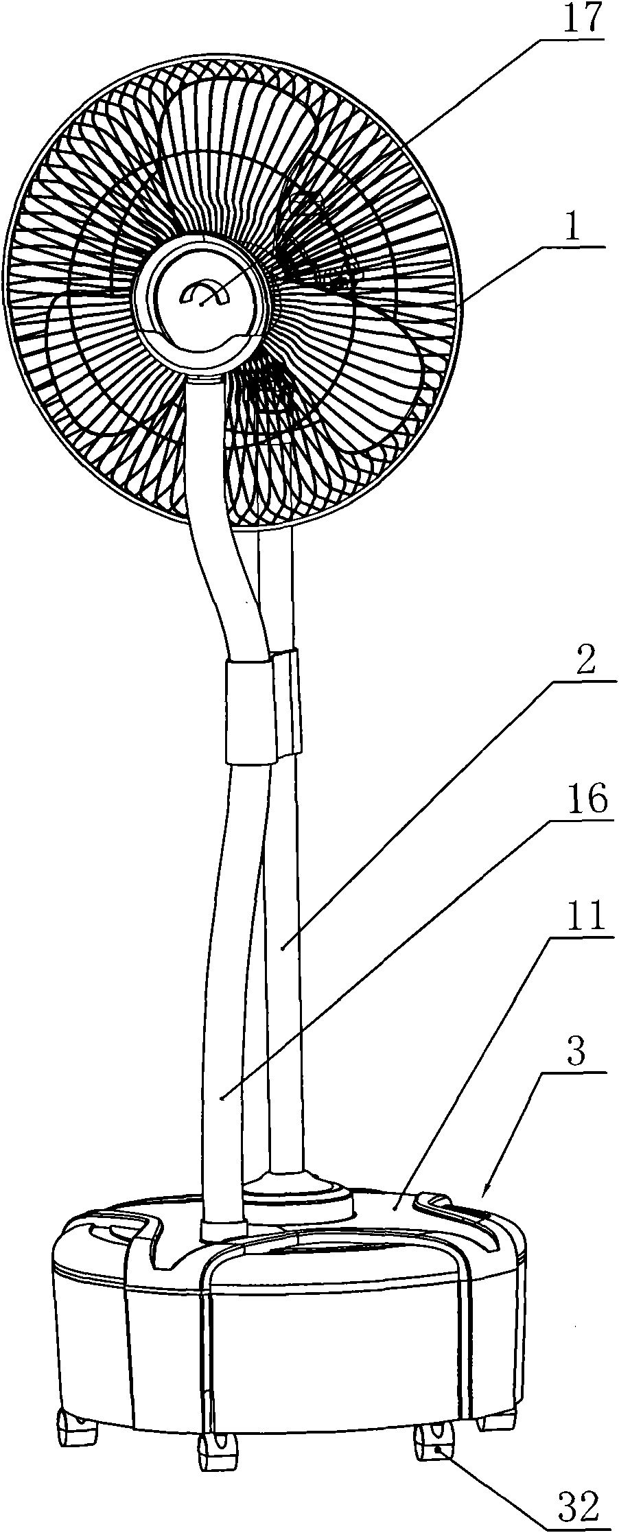
[0038] Such as figure 1 As shown, the humidifying fan includes a fan head 1 , a support column 2 of the fan head and a base 3 , and the support column 2 is supported on the base 3 . The fan head 1 includes a motor main body, fan blades connected to the output shaft of the motor, and a safety net cover fixedly connected to the motor main body and clamped between the fan blades. The central part of the safety net cover is fixed Be connected with diffuse mist cover 17. The fan head 1 is connected to the top of the support column 2 through a positioning device provided on the motor body and can swing on the support column 2 . The support column 2 is made of steel pipe, and conductive wires or control wires (not shown in the figure) are distributed in its lumen.

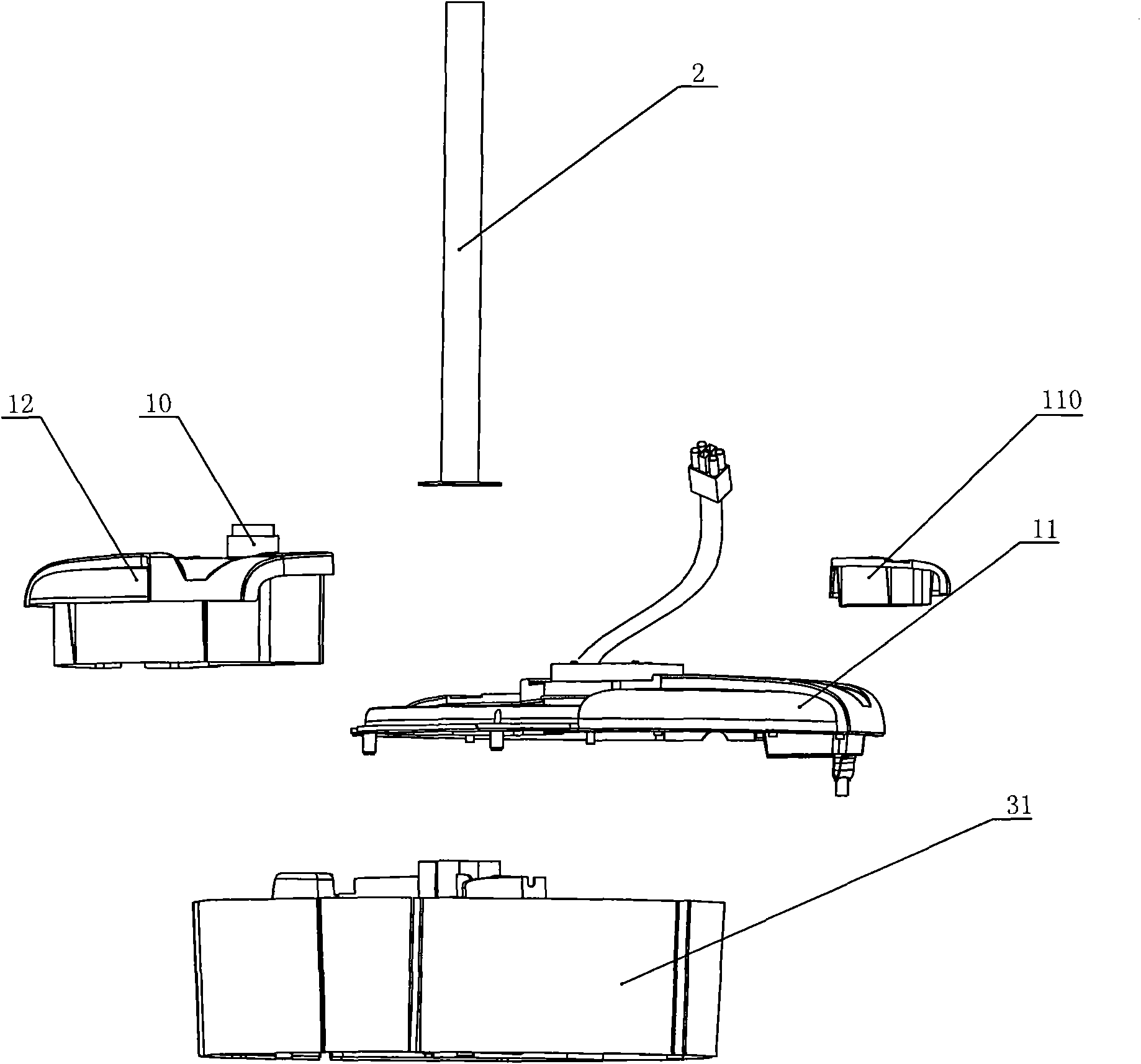
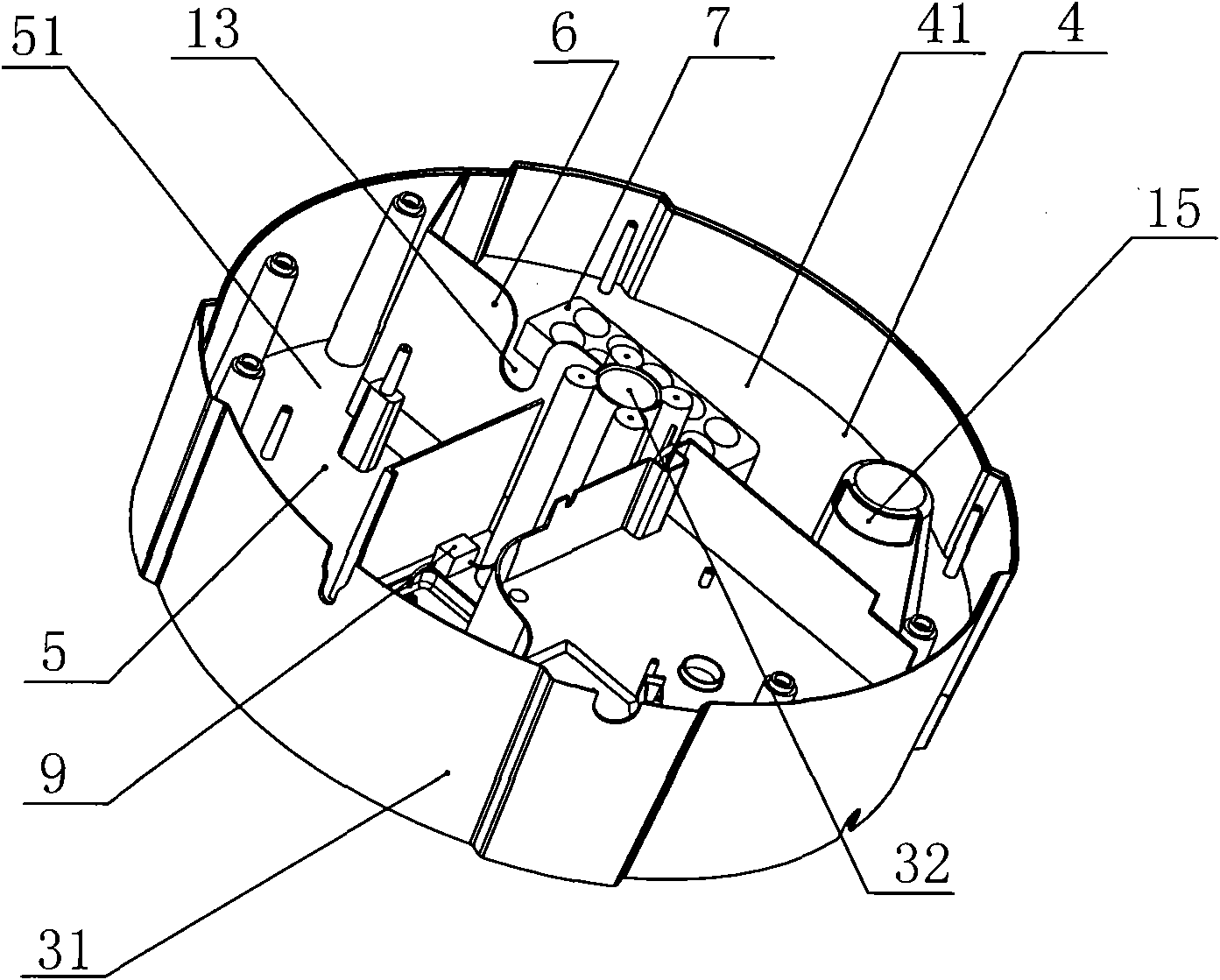
[0039] Such as figure 2 and image 3As shown, the base 3 includes a basin-shaped integral bottom chamber 31 made of plastic injection molding, and the bottom chamber 31 is provided with an atomization chamber 4 and a...

Embodiment 2

[0053] Such as Figure 9 As shown, the humidifying fan includes a fan head 1, a support column 2 of the fan head and a base 3, the support column 2 is supported on the base 3; the base 3 is provided with an atomizing chamber 4 distributed up and down and a water storage chamber 5, wherein the atomization chamber 4 is located above the water storage chamber 5, the atomization chamber 4 and the water storage chamber 5 are separated by a partition wall 6, and the atomization chamber 4 is provided with Ultrasonic nebulizer 7, the base 3 is also provided with a pressurized fan 8 to increase the air pressure in the atomization chamber 4 and can replenish the water in the water storage chamber 5 to the atomization chamber 4 The water supply pump 9 inside, the atomization chamber top cover 41 of the atomization chamber 4 has a mist outlet, one port of the delivery pipe 16 communicates with the mist outlet 10, and the other port extends to the fan head 1 front position.

[0054] Acco...


PUM


Abstract

The invention relates to a humidification fan, which comprises a fan head, a support pillar of the fan head and a base. The supported pillar is supported on the base; the base is provided with a pulverization cavity and a water storage cavity which are distributed at left and right; the pulverization cavity and water storage cavity are separated through a distant wall; the pulverization cavity is internally provided with an ultrasonic atomizer; the base is also provided with a booster fan for increasing air pressure of the pulverization cavity and a charging pump supplementing water in the water storage cavity to the pulverization cavity; the top cap of the pulverization cavity is provided with a fog outlet; one port of the conveying pipe is communicated with the fog outlet; and the other port stretches to the front position of the fan head. The invention has firm integral structure, and improves the convenience in the process of manufacture, assembly and utilization; and the invention can be applied to products of the humidification fan because of the characteristics.

Description

technical field [0001] The invention relates to a humidifying device, in particular to a humidifying fan which can directly humidify a larger space. Background technique [0002] In the prior art, there are various atomizing humidification devices, which basically use an atomizer to atomize water and spread the atomized water vapor into the air. The most traditional and simple method is to let the atomized water vapor diffuse naturally, but more methods are to force the atomized water vapor to diffuse through a fan, which is commonly referred to as an air-conditioning fan. As far as air-conditioning fan products are concerned, there are currently several basic structures. [0003] One of the structures, such as the patent application number 200720176398.X, titled "An Ultrasonic Humidification Air-conditioning Fan", discloses that the air-conditioning fan includes a fan, an ultrasonic atomizing nozzle group, a water storage tank, and a water mist delivery tube cavity. The t...

Claims


Application Information

Patent Timeline
IPC IPC(8): F04D25/08F24F6/12
Inventor 冯泽基
Owner FOSHAN JILING ELECTRIC APPLIANCE TECH CO LTD
Why Eureka
Try Eureka