Fan impeller for cooling

A fan impeller and blade technology, applied in mechanical equipment, machines/engines, liquid fuel engines, etc., can solve problems such as restricting the application of large-diameter impellers, customer installation, inconvenient maintenance, and limited bending resistance

Active Publication Date: 2010-09-15
SHANGHAI ERHUAJIE ELECTROMECHANICAL EQUIP MFG
View PDF7 Cites 4 Cited by
  • Summary
  • Abstract
  • Description
  • Claims
  • Application Information

AI Technical Summary

Problems solved by technology

However, for the blade 130 that is currently pultruded, due to its special process and structural characteristics (such as the petiole adopts a hollow steel pipe, and the diameter of the steel pipe is relatively small, the bending resistance is limited), so it is affected by the bending moment. Easily damaged, which seriously restricts the application of large-diameter impellers, thus becoming a bottleneck in the research and development of large-scale fans
In addition, with this fixing method, the installation angle of the blade 130 can only be adjusted at the installation site, and the height of the blade tip must also be checked, which brings a lot of inconvenience to the customer's installation and maintenance

Method used


Image

  • Fan impeller for cooling
  • Fan impeller for cooling
  • Fan impeller for cooling

Examples


Embodiment Construction

[0016] The technical solutions of the present invention will be further described below in conjunction with the accompanying drawings and embodiments.

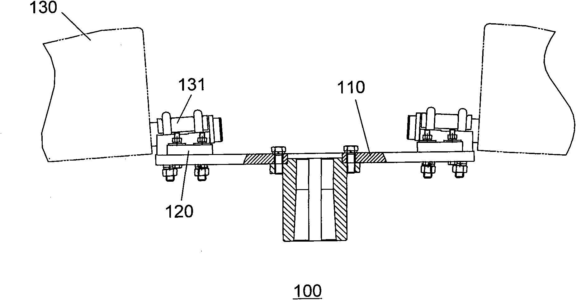
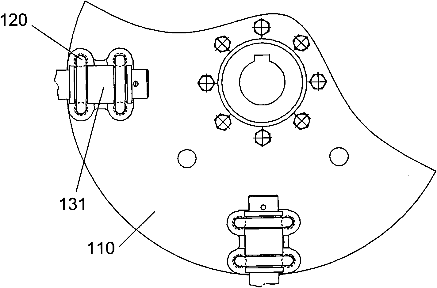
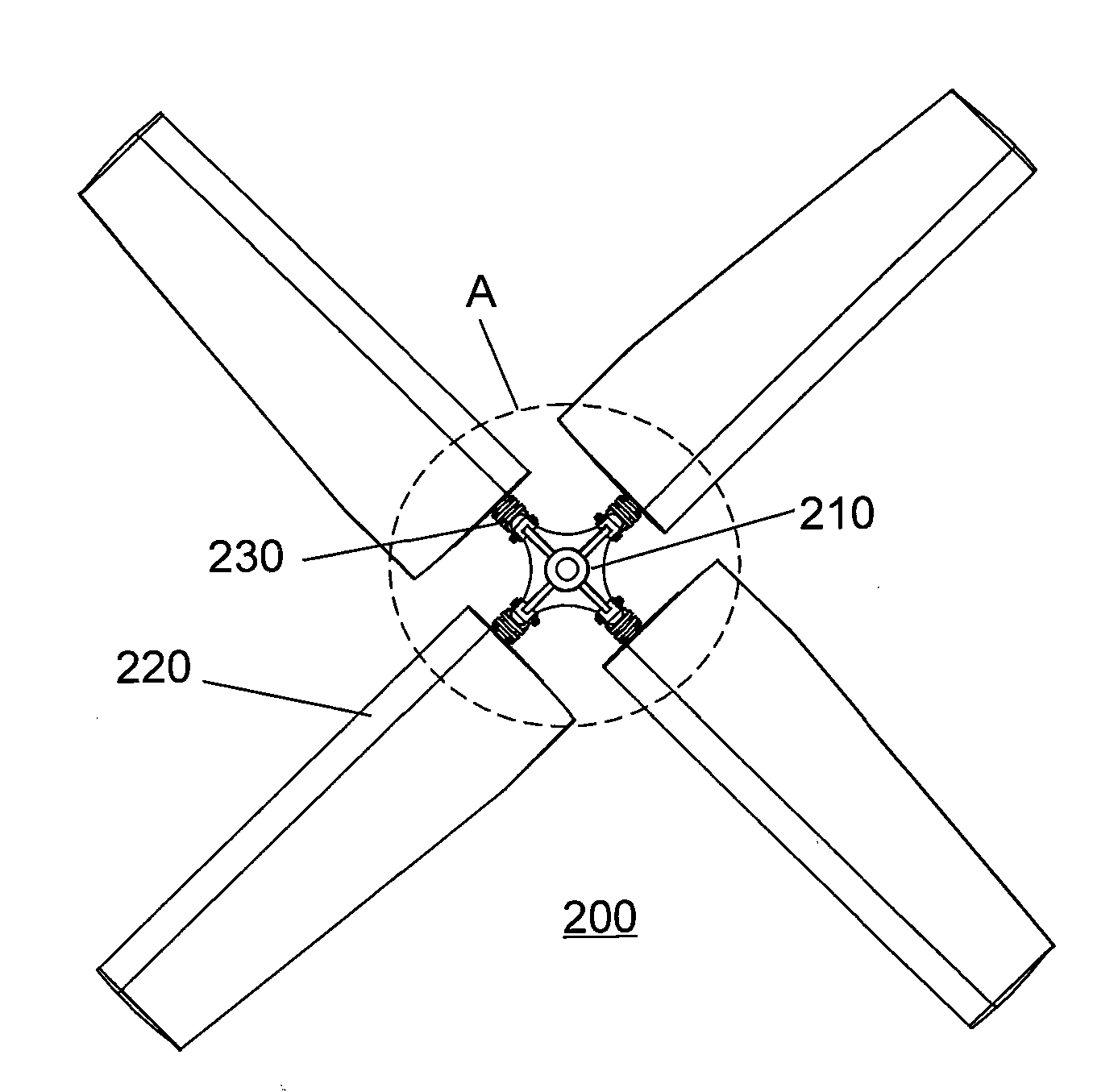
[0017] Please combine Figure 3 ~ Figure 5 As shown, the cooling fan impeller 200 of the present invention includes a hub 210 and several blades 220. Taking four blades 220 as an example, four blade mounts 230 are uniformly arranged around the hub 210, and the petiole 221 of each blade 220 A swing connection part 240 is provided, and is connected to the corresponding blade installation seat 230 through the swing connection part 240 . Specifically, the body of the hub 210 has a cross-shaped structure, and ribs 211 are provided on the edge; each blade mounting seat 230 has a cylindrical structure, which is connected and fixed with the hub 210 in the radial direction, and has a pin hole in the axial direction. The end of the petiole 221 of each blade 220 is provided with a flange 222, and each swing connecting part 240 then incl...


PUM


Abstract

The invention discloses a fan impeller for cooling, wherein, the impeller comprises a wheel hub and a plurality of blades; blade installation seats are arranged around the wheel hub; a swing connection component is arranged on the blade handle of each blade; and swing connection is carried out by the swing connection component and the corresponding blade installation seats. As swing connection is adopted, the blades can swing and shimmy when the fan is operating, thus eliminating the bending moment in the vertical direction of the blade handle, decreasing bending stress of the blade handle, avoiding the damage on the blade handle, and being beneficial for implementing effective application of the large-diameter impeller; and the fan impeller also has the advantage of conveniently adjusting the installation angles of the blades, thus the installation angles can be preset according to the use requirements of a customer before delivery to achieve more convenient and faster field installation.

Description

technical field [0001] The present invention relates to a fan impeller, more specifically, to a fan impeller for cooling. Background technique [0002] At present, the structure of fan impeller 100 of cooling tower or air cooler commonly used in the market is as follows: figure 1 , figure 2 As shown, it includes a circular hub 110, several blade fixing seats 120 and blades 130. The fixing seats 120 are evenly arranged on one end surface of the hub 110, and the petioles 131 are tightly fixed on the corresponding fixing seats 120 by bolts or retaining springs. . The fixed structure of the blade 130 belongs to the cantilever beam type. During operation, the blade 130 cannot flap and vibrate, so there may be a huge vertical and horizontal bending moment at the petiole 131 , so the strength requirement for the petiole 131 is relatively high. However, for the blade 130 that is currently pultruded, due to its special process and structural characteristics (such as the petiole a...

Claims


Application Information

Patent Timeline
Patent Type & Authority Applications(China)
IPC IPC(8): F04D25/08F04D29/26
Inventor 甘钦争朱邦锋徐开元
Owner SHANGHAI ERHUAJIE ELECTROMECHANICAL EQUIP MFG
Why Eureka
Try Eureka