Crankshaft and connecting rod spherical hinging mechanism

A spherical articulation and connecting rod technology, applied in the direction of pivot connection, connecting rod bearing, etc., can solve the problems of increasing equipment operating costs, reducing production efficiency, shortening service life, etc., to extend service life, improve assembly accuracy, and reduce friction. the effect of exercise

Inactive Publication Date: 2010-09-15
TAIYUAN UNIVERSITY OF SCIENCE AND TECHNOLOGY
View PDF1 Cites 2 Cited by
  • Summary
  • Abstract
  • Description
  • Claims
  • Application Information

AI Technical Summary

Problems solved by technology

[0002] At present, the spherical hinge mechanism of the crankshaft and the connecting rod adopts the following figure 1 As shown, it includes crankshaft 1, connecting rod 2, connecting rod cover 3, upper hemispherical sleeve 4, lower hemispherical sleeve 5, driven member 6, between connecting rod cover 3 and upper hemispherical sleeve 4 and connecting rod 2 There is a free spherical sliding fit between the upper and lower hemispherical sleeves 5. This connection increases the freedom of movement, and at the same time causes redundant rotational friction between the spherical surfaces, which can shorten the service life of the upper and lower hemispherical sleeves 4 and 5. , which increases equipment operating costs and reduces production efficiency

Method used


Image

  • Crankshaft and connecting rod spherical hinging mechanism
  • Crankshaft and connecting rod spherical hinging mechanism
  • Crankshaft and connecting rod spherical hinging mechanism

Examples


Embodiment Construction

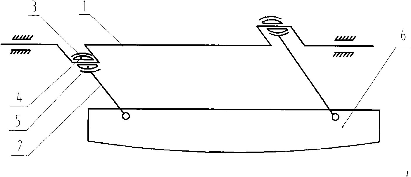
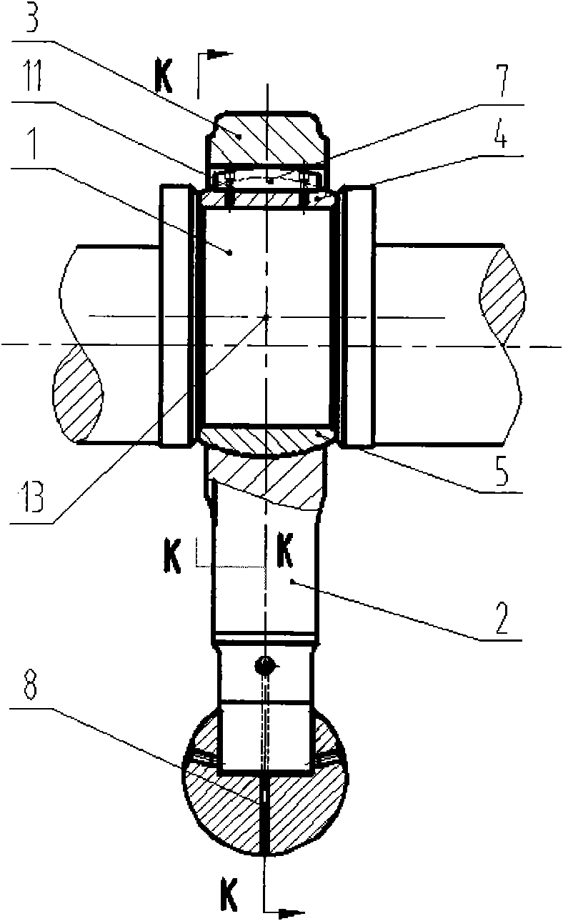
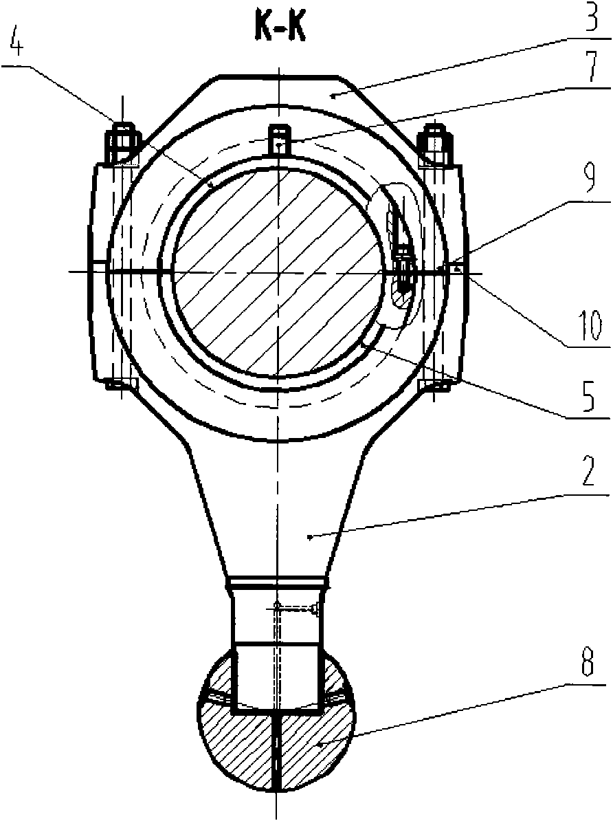
[0012] Such as Figure 2-4 As shown, including crankshaft 1, connecting rod 2, connecting rod cover 3, upper and lower hemispherical sleeves 4, 5, a cuboid is installed between the upper hemispherical sleeve 4 and the contact surface of connecting rod cover 3, and the upper surface axial direction is The circular arc key 7 is connected with the bolt 11 between the arc key 7 and the upper hemispherical cover 4, and the connecting rod 2 lower ends are connected with the connecting rod ball 8. Both sides of the fork-shaped connecting rod 2 upper ends are formed with concave slits 10 and convex slits 9 formed on both sides of the lower end of the connecting rod cover 3 are fitted. When the crankshaft 1 rotates, it drives the connecting rod 2 to swing up and down, and the connecting rod cover 3 and the upper hemispherical sleeve 4 can only swing around the center of rotation 13 and cannot rotate relative to each other in the axial direction.

[0013] In the patent No. "ZL200510012...


PUM


Abstract

The invention discloses a crankshaft and connecting rod spherical hinging mechanism, which belongs to the technical field of mechanical transmission. The mechanism comprises a crankshaft, a connecting rod, a connecting rod cover, an upper semi-spherical sleeve and a lower semi-spherical sleeve, and is characterized in that: an arc key capable of preventing the upper semi-spherical sleeve and the connecting rod cover from moving relatively is arranged between the contact surfaces of the connecting rod cover and the upper semi-spherical sleeve; the arc key is rectangular, and the upper surface of the arc key is in an arc shape in an axial direction; and in addition, concave and convex steps which are engaged are formed between the contact surfaces of the upper end of the fork-shaped connecting rod and the connecting rod cover. The mechanism has the advantages of preventing rotation between the upper and lower semi-spherical sleeves and the connecting rod cover and the connecting rod, making the upper and lower semi-spherical sleeves, the connecting rod cover and the connecting rod only swing around a turning center, effectively reducing friction motion between spherical surfaces and prolonging the service life of spherical kinematic pairs.

Description

technical field [0001] The invention belongs to the technical field of mechanical transmission, and in particular relates to a crankshaft and connecting rod spherical hinge mechanism. Background technique [0002] At present, the spherical hinge mechanism of the crankshaft and the connecting rod adopts the following figure 1 As shown, it includes crankshaft 1, connecting rod 2, connecting rod cover 3, upper hemispherical sleeve 4, lower hemispherical sleeve 5, driven member 6, between connecting rod cover 3 and upper hemispherical sleeve 4 and connecting rod 2 There is a free spherical sliding fit between the upper and lower hemispherical sleeves 5. This connection increases the freedom of movement, and at the same time causes redundant rotational friction between the spherical surfaces, which can shorten the service life of the upper and lower hemispherical sleeves 4 and 5. , Increased equipment operating costs and reduced production efficiency. Contents of the invention...

Claims


Application Information

Patent Timeline
Patent Type & Authority Applications(China)
IPC IPC(8): F16C11/06F16C9/04
Inventor 孙斌煜刘卯生孙尧陈攀张洪任志峰许春园郑天虎孟凡震
Owner TAIYUAN UNIVERSITY OF SCIENCE AND TECHNOLOGY
Why Eureka
Try Eureka