
Variable-effective-action-area hydraulic cylinder

An effective, hydraulic cylinder technology, applied in the direction of fluid pressure actuation devices, fluid pressure actuation system components, mechanical equipment, etc., can solve complex pump source pressure and flow control devices, industrial field electromechanical equipment disadvantage, pump source pressure Or the flow rate is not adjustable, etc., to achieve the effect of reducing matching problems, reducing output, and simplifying the system

Inactive Publication Date: 2018-11-23
HARBIN INST OF TECH
View PDF7 Cites 2 Cited by
  • Summary
  • Abstract
  • Description
  • Claims
  • Application Information

AI Technical Summary

Problems solved by technology

[0003] The effective area of ​​the hydraulic cylinder is one of the main parameters of the hydraulic cylinder. The effective area of ​​the traditional hydraulic cylinder is fixed after the structural design, and the effective area cannot be changed during the use of the hydraulic cylinder, which greatly reduces the hydraulic cylinder. scope of application
In many industrial or electromechanical equipment, hydraulic cylinders are often required to output different forces and speeds at different times during the working process. If the area of ​​the hydraulic cylinder is fixed, the force and speed output by the hydraulic cylinder can only be changed by controlling the pressure and flow of hydraulic oil. , the problem brought about is the complicated pump source pressure and flow control device, and in many occasions the pressure or flow of the pump source cannot be adjusted, which is unfavorable to the work of industrial sites and electromechanical equipment

Method used


Image

  • Variable-effective-action-area hydraulic cylinder
  • Variable-effective-action-area hydraulic cylinder
  • Variable-effective-action-area hydraulic cylinder

Examples


Embodiment 1

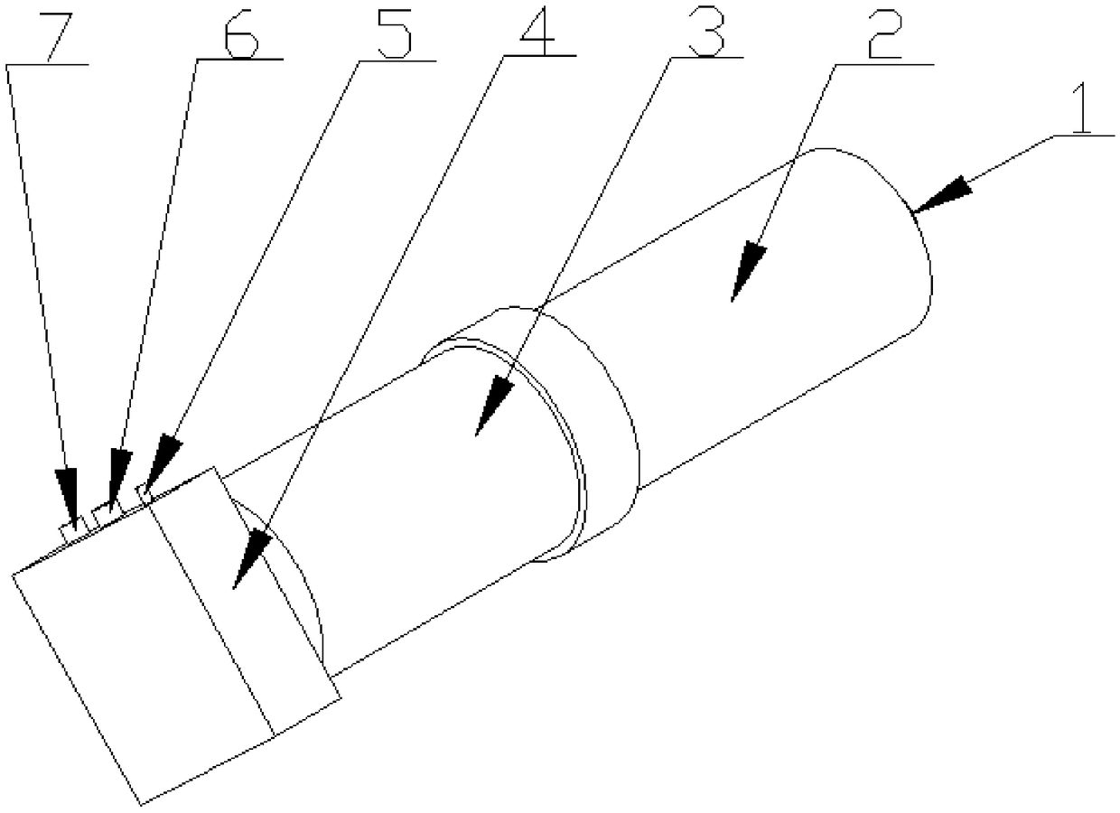
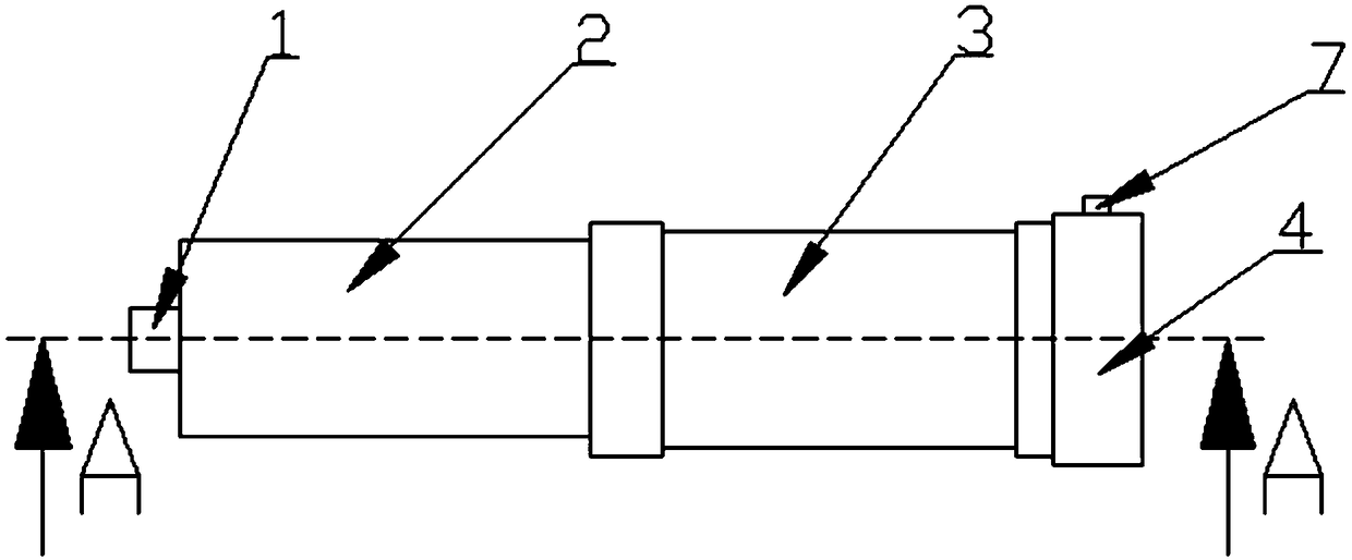
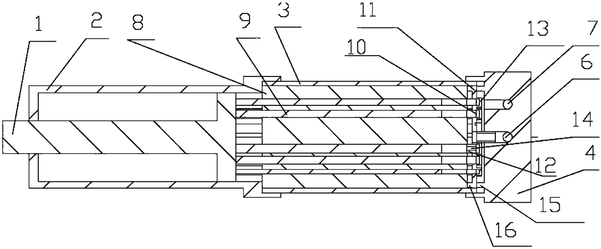
[0023] Such as Figure 1-7 As shown, a hydraulic cylinder with a variable effective area includes a piston rod 1 and a hydraulic cylinder. The hydraulic cylinder is divided into a hydraulic cylinder front section 2, a hydraulic cylinder middle section 3 and a hydraulic cylinder rear section 4. The hydraulic cylinder front section 2 and the hydraulic cylinder The front part of the middle section 3 is detachably connected, and the tail of the middle section 3 of the hydraulic cylinder is detachably connected with the rear section 4 of the hydraulic cylinder. The rear section 4 of the hydraulic cylinder has a pump source hydraulic oil port 6 and a zero-pressure hydraulic oil port 7. Piston rod 1 is installed in the internal clearance, and the secondary hydraulic cylinder cylinder 8 is installed in the internal clearance of the middle section 3 of the hydraulic cylinder. A certain number of through holes are opened in the cylinder cylinder 8 of the secondary hydraulic cylinder. Th...


PUM


Abstract

The invention discloses a variable-effective-action-area hydraulic cylinder, which adopts an integrated structure of a plurality of second-stage hydraulic cylinders and a first-stage hydraulic cylinder, wherein the plurality of second-stage hydraulic cylinders jointly use a porous cylinder body, and use an oil inlet, and an oil distribution mode is as follows: one of a plurality of small electromagnetic switches corresponds to one second-stage hydraulic cylinder, and finally all the structures are configured in a hydraulic three-stage hydraulic cylinder to form the variable-effective-action-area hydraulic cylinder. The second-stage hydraulic cylinder is arranged in the middle section of the three-stage main hydraulic cylinder, and adopts a plunger type structure. The variable area technology of the hydraulic cylinder is realized, and the problem that the traditional hydraulic cylinder can not change the effective action area after the structure is determined is solved; the second-stagehydraulic cylinder can realize one-to-one control and group control, and the control mode is more flexible and simple; the problem of only relying on an oil source to adjust the output of the hydraulic cylinder is solved, so that the system is more energy-saving and reliable.

Description

technical field [0001] The invention relates to a variable effective area hydraulic cylinder. Background technique [0002] Hydraulic technology has the advantages of large output, high response and high power density, and is widely used in fields such as industry and large-scale electromechanical equipment. As one of the core components of hydraulic technology, the actuator hydraulic cylinder occupies an important position in hydraulic technology. Irreplaceable position, the hydraulic cylinder is an important bridge for converting hydraulic energy into appropriate mechanical energy, which is directly related to whether the hydraulic system can work according to people's wishes. At present, there are many kinds of hydraulic cylinders, which can be mainly divided into the following categories: according to the structure, they can be divided into piston cylinders, plunger cylinders and swing cylinders. Among them, the piston cylinder and plunger cylinder output linear motion, ...

Claims


Application Information

Patent Timeline
IPC IPC(8): F15B15/14F15B15/20F15B21/04
CPCF15B15/14F15B15/1428F15B15/149F15B15/20F15B21/04
Inventor 丛大成李加启杨志东张燕燕
Owner HARBIN INST OF TECH
Learn More