clutch pedal unit

A technology of clutch pedal and clutch, which is applied in the direction of control devices, mechanical control devices, instruments, etc., to achieve the effect of low cost

Inactive Publication Date: 2018-03-02
ROBERT BOSCH GMBH
View PDF7 Cites 0 Cited by
  • Summary
  • Abstract
  • Description
  • Claims
  • Application Information

AI Technical Summary

Problems solved by technology

Disadvantageously, this embodiment only achieves a linearly increasing profile of the pedal force with respect to the pedal path

Method used


Image

  • clutch pedal unit
  • clutch pedal unit
  • clutch pedal unit

Examples


Embodiment Construction

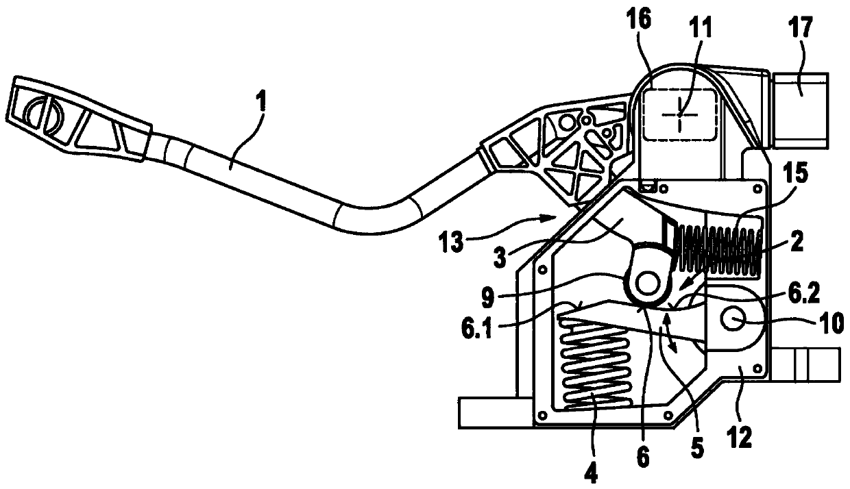
[0019] figure 1 A sectional view of a first embodiment of the clutch pedal device of the present invention is shown.

[0020] The clutch pedal arrangement is used to electronically control a clutch arranged in the drive train of the vehicle and to provide the driver with a pedal feel when actuating the clutch pedal as in a hydraulically actuated clutch pedal.

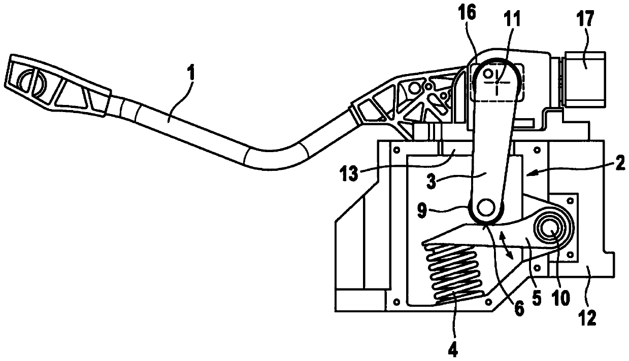
[0021] The clutch pedal arrangement has a rotatably mounted clutch pedal 1 and a mechanism 2 for generating a predetermined profile of the pedal force with respect to a pedal path or a pedal displacement of the clutch pedal 1 . The mechanism 2 comprises a pedal arm 3 which is non-rotatably connected to the clutch pedal 1 and which can move against spring force.

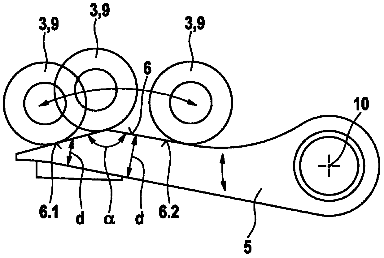
[0022] It is proposed according to the invention that the pedal arm 3 acts on a counterforce-acted, rotatably mounted lever arm 5 and moves in translation on the contour 6 of the lever arm 5 when the clutch pedal 1 is actuated.

[0023] The counterforce actin...


PUM


Abstract

Clutch pedal devices are known which comprise a rotatably mounted clutch pedal and means for generating a specified pedal force curve over the pedal path, said means comprising a pedal arm which is non-rotatably connected to the clutch pedal and which can be moved against a spring force of a helical spring. Disadvantageously, only a linearly increasing pedal force curve over the pedal path can be achieved using said design. Thus, a pedal sensation is produced which strongly deviates from the pedal sensation produced when using a conventional clutch pedal which hydraulically actuates the clutch. In the clutch pedal device according to the invention, the pedal force curve over the pedal path also has a section with a negative slope after a section with a positive slope. In this manner, a pedal sensation is produced which strongly resembles the pedal sensation when actuating a conventional clutch pedal which hydraulically actuates the clutch. According to the invention, the pedal arm (3) acts on a rotatably mounted lever arm (5), to which a counter force is applied, and is moved on a contour (6) of the lever arm (5) when the clutch pedal (1) is actuated.

Description

technical field [0001] The invention relates to a clutch pedal device. Background technique [0002] A clutch pedal arrangement is already known from DE 102 32 212 A1 with a rotatably mounted clutch pedal and a mechanism for generating a predetermined profile of the pedal force with respect to the pedal path, said mechanism comprising a non-rotatable connection to the clutch pedal The pedal arm is movable against the spring force of the coil spring. The disadvantage is that this embodiment only allows a linearly increasing profile of the pedal force with respect to the pedal path. This results in a pedal feel that deviates considerably from the pedal feel when the clutch pedal of a conventional hydraulically actuated clutch is actuated. Contents of the invention [0003] In contrast, the clutch pedal arrangement according to the invention has the advantage that the profile of the pedal force over the pedal path also includes a section with a negative slope after a sectio...

Claims


Application Information

Patent Timeline
Patent Type & Authority Patents(China)
IPC IPC(8): B60K23/02B60K26/02G05G1/30G05G5/03
CPCB60K23/02B60K26/021G05G1/30G05G5/03
Inventor M·赫拉夫卡
Owner ROBERT BOSCH GMBH
Why Eureka
Try Eureka