
Lens device

A technology of lens and moving lens, which is applied in installation, television, optics, etc., can solve problems such as adjustment position deviation, and achieve the effect of preventing adjustment position deviation and preventing bad conditions

Inactive Publication Date: 2010-09-15
FUJI PHOTO OPTICAL CO LTD
View PDF1 Cites 7 Cited by
  • Summary
  • Abstract
  • Description
  • Claims
  • Application Information

AI Technical Summary

Problems solved by technology

Therefore, when the lock knob is screwed in, the zoom ring may move from the adjustment position or the focus ring may move from the adjustment position together with the lock knob, and there is a problem that the focus position and focal length are shifted from the adjustment position before the lock knob is locked.

Method used


Image

  • Lens device
  • Lens device
  • Lens device

Examples


Embodiment Construction

[0026] Hereinafter, embodiments of the lens device for a surveillance camera according to the present invention will be described in detail with reference to the drawings.

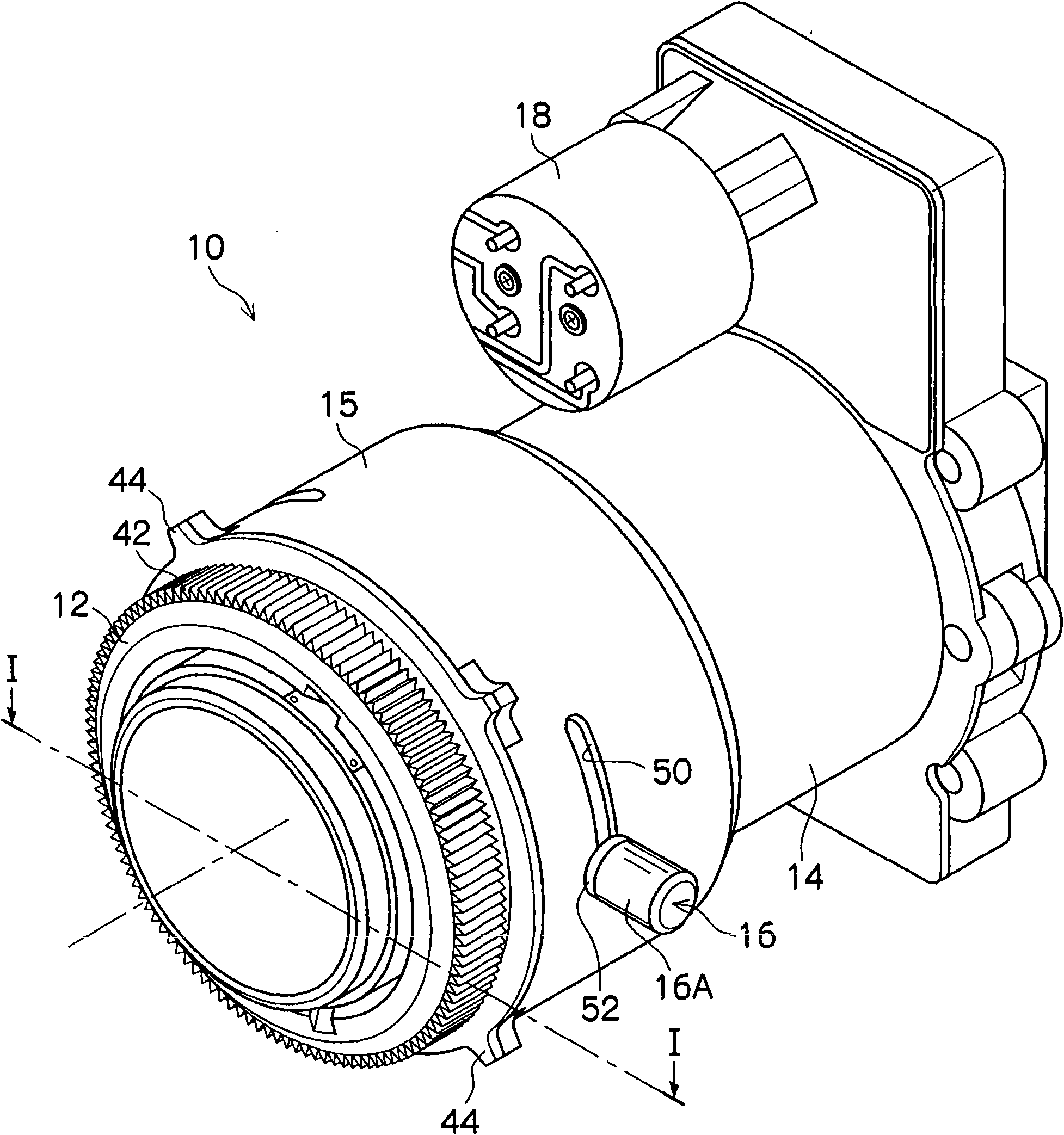
[0027] figure 1 It is a perspective view showing the structure of the monitoring lens device to which the present invention is applied and the surrounding parts. The monitoring lens device 10 shown in this figure is mainly used in a camera device for monitoring, and a focus ring 12, a zoom ring 14, and a lock button 16 are provided on the outer peripheral portion of a fixed cylinder that supports a focus lens or a zoom lens inside. Wait. Furthermore, a driving device 18 for driving the infrared filter is provided in the monitoring lens device 10 .

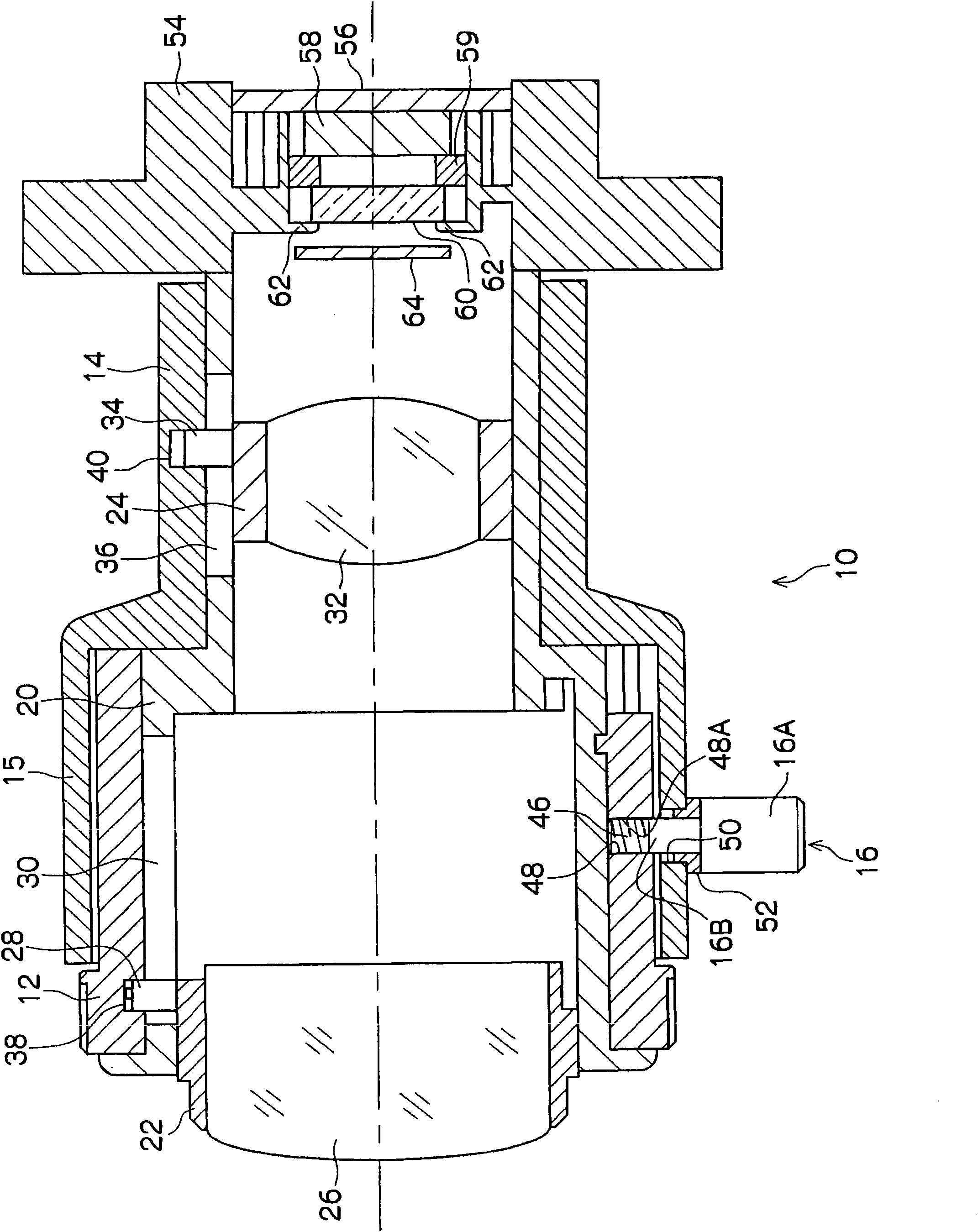
[0028] figure 2 It is a cross-sectional view showing the structure of the monitoring lens in detail, showing along the optical axis and figure 1 The cross-section of the plane shown by the dot-dash line I-I. As shown in the drawing (the same figure), the mo...


PUM


Abstract

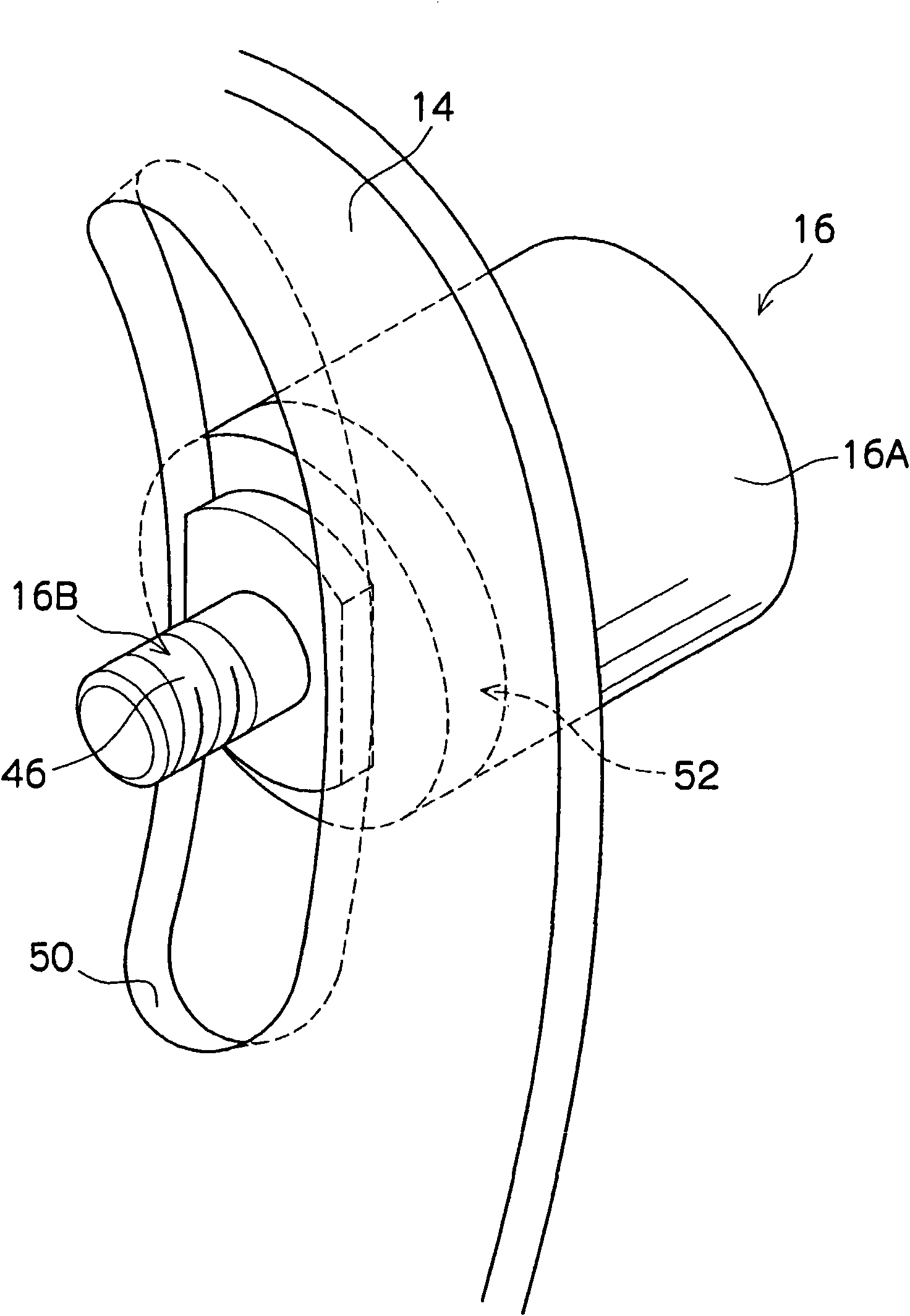
The present invention provides a lens device, having a locking mechanism for locking an operating ring for operating a presetting lens or diaphragm by screwing in a lock knob, and capable of aligning the position of locking the operating ring by mounting a spacer embedded in a groove of the operating ring through which the lock knob passes on the lock knob. A monitoring lens device (10) includes a focus ring (12) that is provided in an outer circumferential portion of a fixed cylinder (20) and a zoom ring (14) that is provided in an outer circumferential portion of the focus ring. A screw hole (48) that is engaged with a shaft portion (16B) of the lock knob (16) is formed in the focus ring (12), and an opening portion (50) (long groove) through which the lock knob (16) passes is formed in the zoom ring (14). The spacer (52) is attached to the lock knob (16) and a convex portion (104) of the spacer (52) is fitted into the opening portion (50).

Description

technical field [0001] The present invention relates to a lens device used in a surveillance video camera or the like provided with a locking mechanism for locking an operation ring such as a focus ring or a zoom ring at a predetermined position. Background technique [0002] In recent years, small surveillance cameras (CCTV cameras for surveillance) have been widely used in financial institutions, various stores, and the like. The monitoring lens device used in this monitoring camera is provided with a focus ring for adjusting the focus position and a zoom ring for adjusting the focal length on the outer periphery of its lens barrel (fixed tube). The focus position and focal length are adjusted by operating these focus rings and zoom rings. [0003] Furthermore, the monitoring camera is housed in the case and installed on a wall or the like, and captures images of the outside so that the front of the monitoring camera lens unit faces the outside from the opening provided i...

Claims


Application Information

Patent Timeline
Patent Type & Authority Applications(China)
IPC IPC(8): G02B7/04H04N5/225
CPCG02B7/10
Inventor 佐藤真澄大卫
Owner FUJI PHOTO OPTICAL CO LTD
Learn More