
Welder for rolling facility, rolling facility, and rolling method

一种轧制设备、焊机的技术,应用在轧制设备用焊机领域,能够解决未能提示最佳方式、没有明示也考虑到、阻碍生产率等问题,达到设备费用减少、时间短、生产效率提高的效果

Active Publication Date: 2010-09-15
JP STEEL PLANTECH CO
View PDF5 Cites 14 Cited by
  • Summary
  • Abstract
  • Description
  • Claims
  • Application Information

AI Technical Summary

Problems solved by technology

[0014] In the above-mentioned Patent Document 1, although a method of reducing the loss of defective parts in steel plate rolling using a reversing rolling mill to improve the yield is suggested, the most advantageous countermeasure that also takes productivity into consideration is not explicitly stated.
If the leader is attached to both the front end and the rear end, the yield rate will be significantly improved, but conversely, it takes time to process the leader remaining on the inner peripheral side of the coil, hindering productivity.
In other words, the optimal sequence for maximizing productivity in relation to the welding of the leader tape and the subsequent separation has not been found in the past.
In addition, for example, as a welding machine for welding a leader tape to a rolled steel plate, the best method for actualization has not been suggested.

Method used


Image

  • Welder for rolling facility, rolling facility, and rolling method
  • Welder for rolling facility, rolling facility, and rolling method
  • Welder for rolling facility, rolling facility, and rolling method

Examples


Embodiment Construction

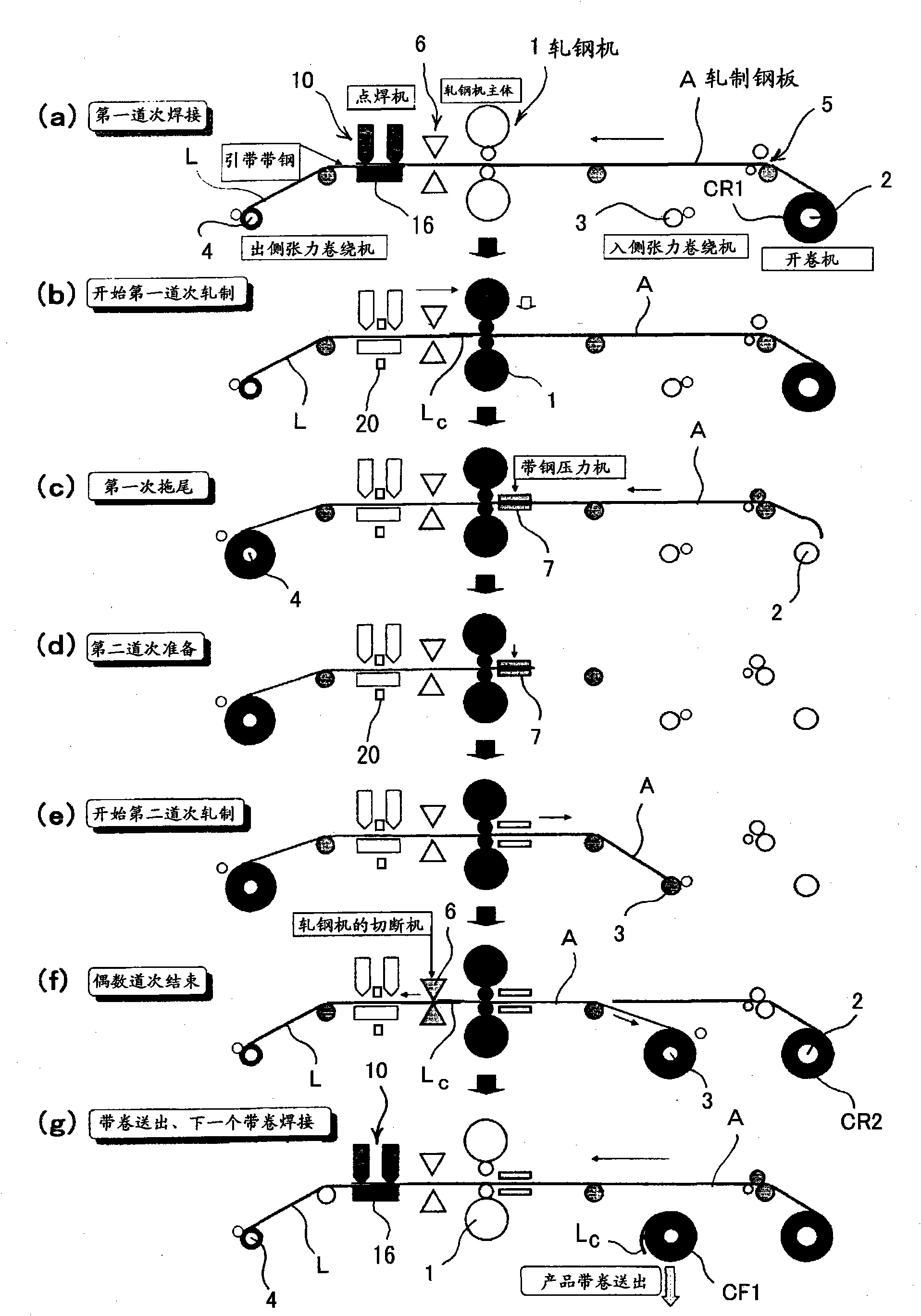
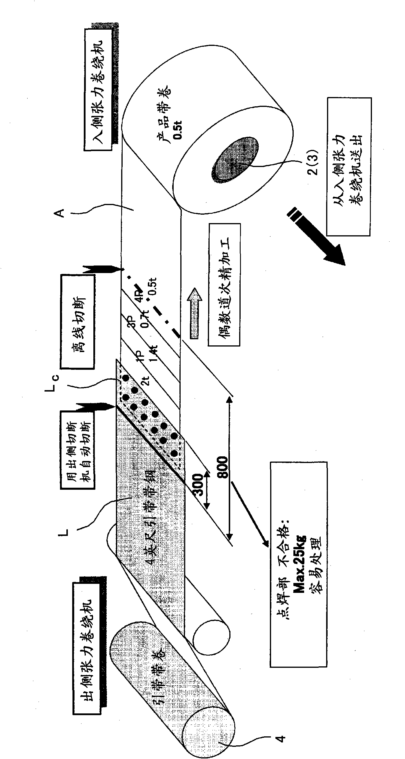
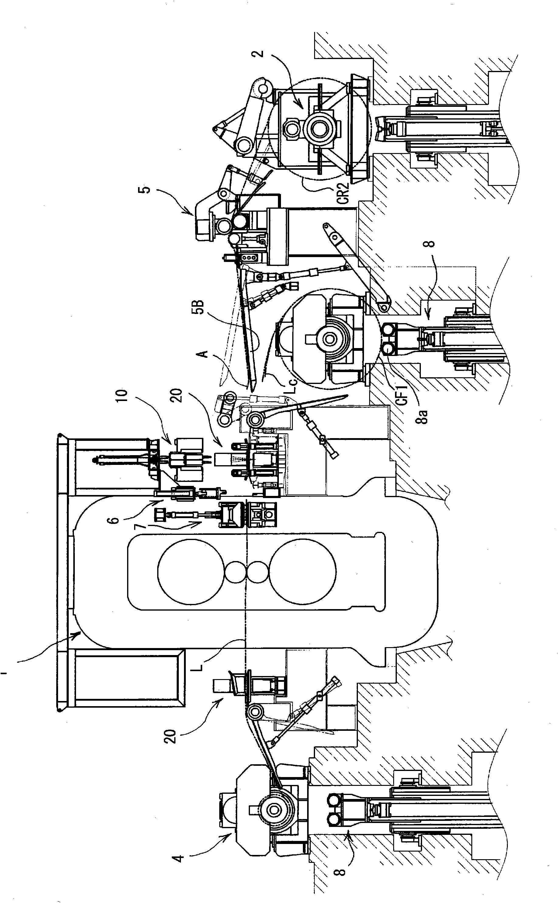
[0065] Figure 1 to Figure 11 The rolling method and rolling facility related to the reversing cold rolling of ordinary steel which show one embodiment of this invention. figure 1 is a diagram conceptually showing a rolling method and a rolling facility according to an embodiment of the present invention, figure 2 is a diagram showing the basic concept of important parts in this rolling method, image 3 It is a figure which exemplifies the overall view of a rolling facility. Figure 4 ~ Figure 7 It is a detailed diagram showing the structure of the welder 10 and its surroundings in the rolling facility, Figure 8 It is a perspective view showing the welding machine 10 and the like together with the rolling mill 1 . also, Figure 9 ~ Figure 11 It is a figure explaining the effect of the rolling method and rolling facility shown in figure.

[0066] Such as figure 1 As shown, in the illustrated equipment, there are rolling mill (rolling mill main body) 1, uncoiler (uncoi...


PUM


Abstract

The invention provides a rolling method including the most advantageous procedure for the welding operation and the subsequent separation of a leader strip. The rolling facility welder (10) performs a series welding operation with a back bar disposed below a pass line and a welding gun disposed over the pass line, thereby to weld a plurality of points simultaneously. The rolling method joints a leader portion (L) held in an exit welder (4) and the tip of a rolled sheet (A) by the spot welder (10), and the rolled sheet (A) is finished in a pass of an even number toward an entrance winder (3).

Description

technical field [0001] The present invention relates to a welding machine for a rolling facility that rolls a rolled steel sheet (strip, etc.) reciprocally through a rolling mill (reversing rolling mill), a rolling facility equipped with the same, and a rolling method. Background technique [0002] The rolling (reversible rolling) of strip steel (rolled steel plate) using a reversing rolling mill is to use a rolling mill (rolling mill main body), an uncoiler (uncoiler) installed on its entry side, and a Winding machines on the entry and exit sides, etc. Since the rolling is carried out while applying tension to the strip, the front end of the strip is held by being wound on the exit side coiler for 2 to 3 turns at the beginning of the first pass. At the beginning, the end portion of the strip is wound on the entry side coiler for 2 to 3 turns and held. Thereafter, rolling is performed reciprocatingly in a plurality of passes in a state where the leading end portion and the...

Claims


Application Information

Patent Timeline
Patent Type & Authority Applications(China)
IPC IPC(8): B21B15/00B21B1/32B21C47/26B23K11/11B23K101/16
CPCB21C47/247B21B1/32B23K2201/16B23K11/11B21B15/0085B23K2101/16
Inventor 吉川种浩
Owner JP STEEL PLANTECH CO
Learn More