
Method for determining and displaying steering indications and steering indicator for implementing said method.

A technology of indicators and displays, applied in the field of driving rotary-wing aircraft, can solve problems such as damaged engine operating limits, increased turbine engine power requirements, etc.

Active Publication Date: 2010-09-22
EUROCOPTER
View PDF6 Cites 4 Cited by
  • Summary
  • Abstract
  • Description
  • Claims
  • Application Information

AI Technical Summary

Problems solved by technology

This leads to an increase in the power requirements of the turbine engine, which can lead to very quickly reaching the operating limit which damages said engine

Method used


Image

  • Method for determining and displaying steering indications and steering indicator for implementing said method.
  • Method for determining and displaying steering indications and steering indicator for implementing said method.
  • Method for determining and displaying steering indications and steering indicator for implementing said method.

Examples


Embodiment Construction

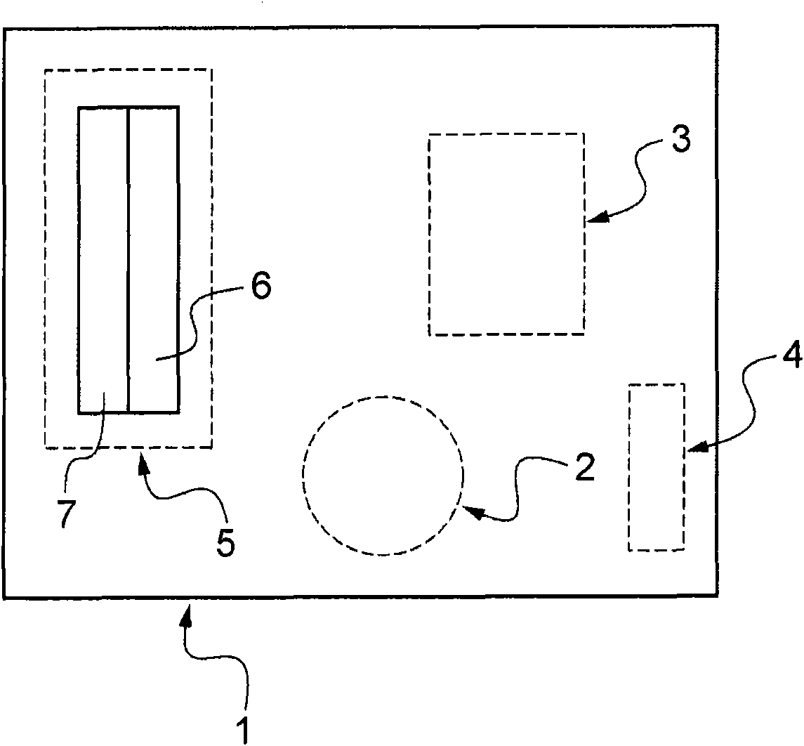
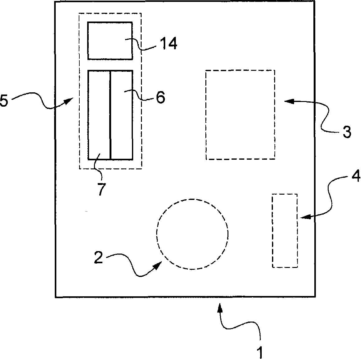
[0068] Figure 1a An example of a generic screen 1 of an aircraft instrument panel comprising a flight indicator according to the invention is shown. In particular, the general screen 1 comprises various indicators 2, 3 and 4, which are known per se and which can be used to control the operation and navigation of the aircraft.

[0069] The flight indicators include, for example, a first-limit indicator (FLI) associated with the display screen 5 . The first-limit value indicator, as briefly described above, is well known and will therefore not be described in detail.

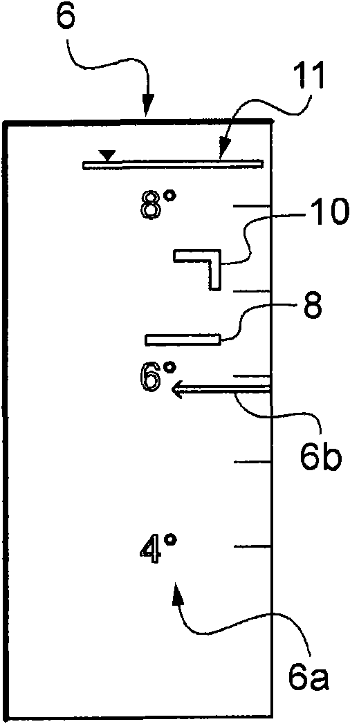
[0070] The display screen 5 has a first dial 6 on which a movable scale 6a is displayed, such as Figures 2 to 6 shown in . The movable scale 6a has a vertical graduated display of the position of the pitch P. The movable scale 6a moves relative to the fixed reference 6b on the display screen 5 as a function of the setting of the pitch P, and then the level of the movable scale 6a represented by the current po...


PUM


Abstract

The present invention relates to a pilot assistance method for giving assistance in piloting a rotary wing aircraft, the method consisting in using a scale with collective pitch graduations that is movable on a display screen to indicate the position of the collective pitch, in determining the desynchronization pitch, in using a maximum limit value and a minimum limit value for the speed of rotation of the rotor, in transforming the maximum limit value and the minimum limit value in real time and as a function of physical flight parameters respectively into a bottom limit position and a top limit position for the collective pitch, and when a determined difference appears between the real value and the reference value Nr0 for the speed of rotation of the rotor, in displaying at least one item of corrective information about the adjustment of the collective pitch.

Description

technical field [0001] The present invention relates to the general technical field of driving a rotary wing aircraft, in particular, to the general technical field of flight instruments. Aircraft pilots use these instruments to monitor the environment and technical parameters related to flight. These instruments firstly allow the pilot of the aircraft to be aware of any misoperation of equipment, such as the aircraft's engine or other parts of the equipment, and secondly assist the pilot during the various piloting phases of said aircraft. Background technique [0002] For example, when flying a helicopter, it is necessary to monitor many instruments on the instrument panel, most of which are used to display the operation of the engine units or other parts of the aircraft equipment. For physical reasons, the pilot of the aircraft has to take into account at each moment during the flight a number of limiting situations which generally depend on the state of the aircraft and...

Claims


Application Information

Patent Timeline
Patent Type & Authority Applications(China)
IPC IPC(8): B64D43/00
CPCG01C23/005
Inventor K·德博诺M·科拉德
Owner EUROCOPTER
Learn More