
Tractor support beam structure on elevator

A technology for supporting beams and traction machines. It is used in elevators, transportation, and packaging in buildings. It can solve the problems of vibration and inward turning of traction machines, eliminate the possibility, and ensure normal operation and safe use. Effect

Inactive Publication Date: 2010-09-22
三六零安全科技股份有限公司
View PDF7 Cites 2 Cited by
  • Summary
  • Abstract
  • Description
  • Claims
  • Application Information

AI Technical Summary

Problems solved by technology

[0002] On the elevator, the two ends of the traction machine support beam extend into the shelving hole on the inner wall of the hoistway, and then fill the shelving hole with concrete to realize the fixation of the traction machine support beam. Generally, there are two traction machine support beams. Set in parallel at intervals, between two support beams, there are multiple machine beams installed vertically, and traction machines are installed on the multiple machine beams, and the traction machine support beams bear the load of the traction machine, machine beams, car, The weight of the entire elevator system, coupled with the vibration of the traction machine during operation, will cause the support beam of the traction machine to have a risk of turning inwards at a relatively high height

Method used


Image

  • Tractor support beam structure on elevator
  • Tractor support beam structure on elevator
  • Tractor support beam structure on elevator

Examples


Embodiment Construction

[0011] The structure of the present invention will be further described below in conjunction with the accompanying drawings.

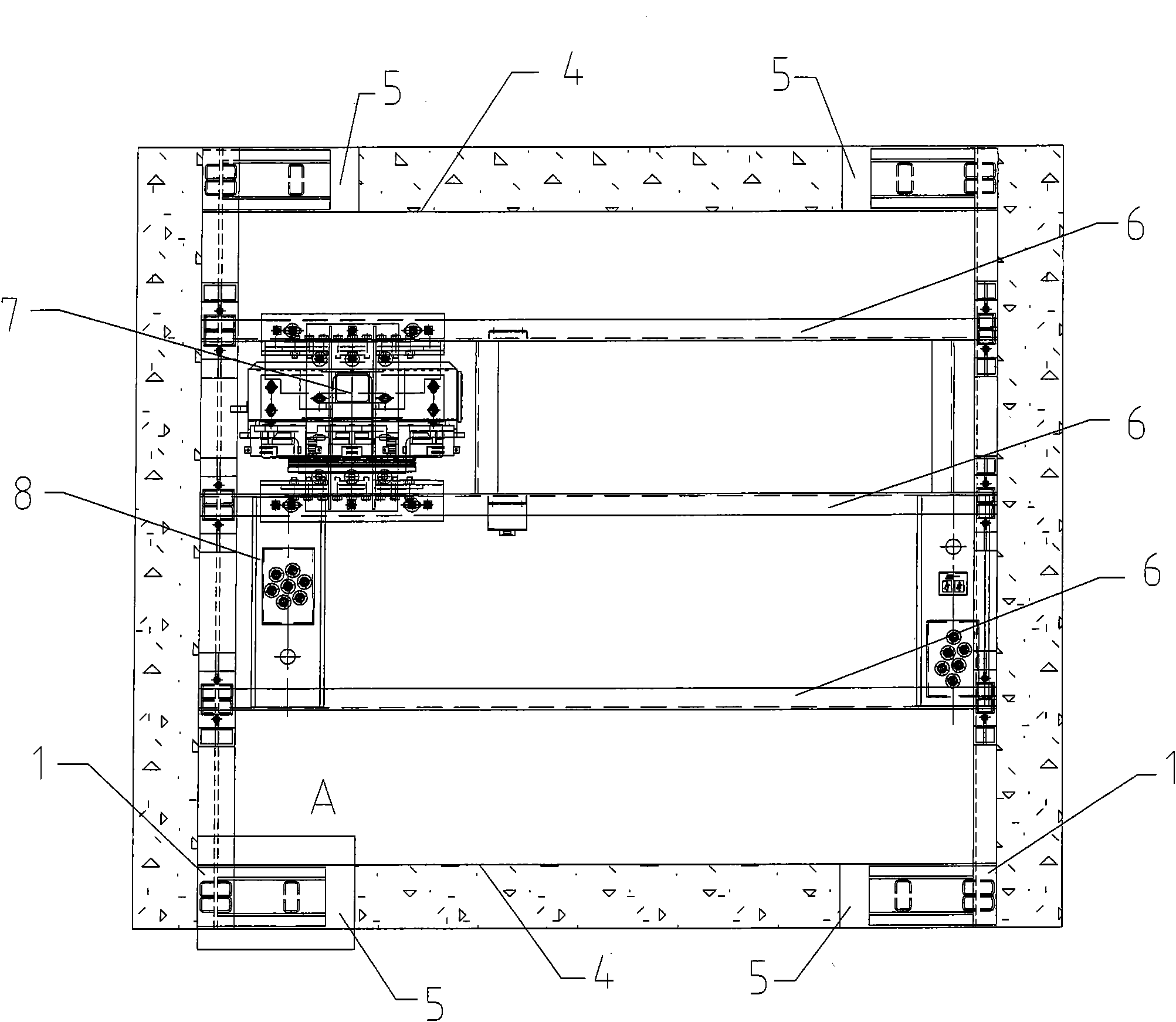
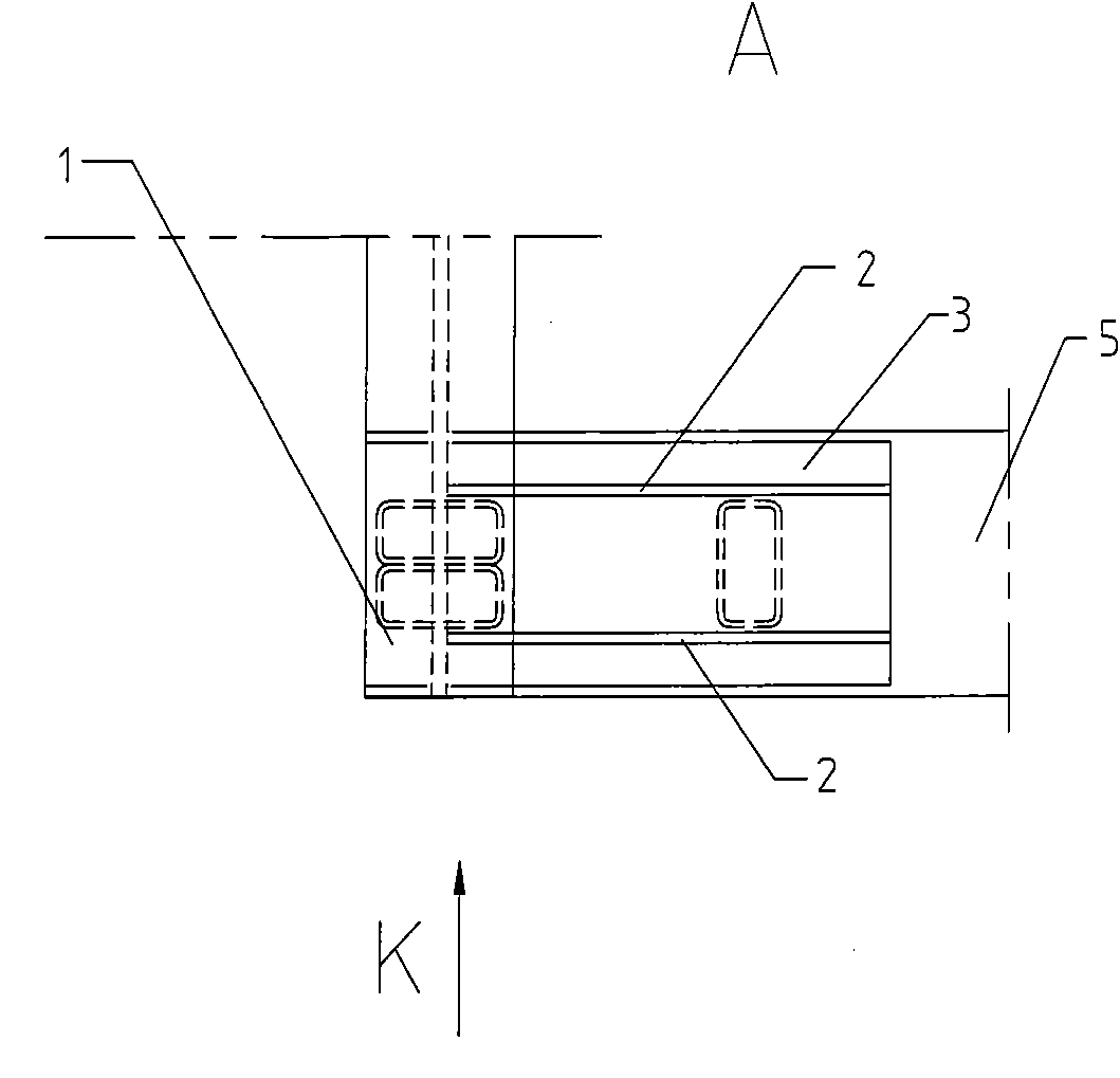
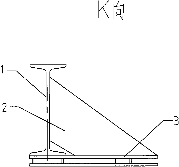
[0012] see Figure 1-3 As shown, the supporting beam structure of the traction machine on the elevator includes a supporting beam 1, and there are two supporting beams 1, which are arranged in parallel and spaced apart. Two pairs of shelving holes 5 oppositely arranged are opened on the inner wall 4 of the hoistway, as shown in FIG. figure 1 As shown, the two ends of each support beam 1 are respectively fixedly extended in the shelving holes 5, and a plurality of spaced shelving beams 6 are vertically arranged on the two support beams 1, and two adjacent shelving beams 6 are arranged vertically on the two support beams 1. The traction machine 7 is carried on the machine beam 6, and the rope head assembly fixing seat 8 for fixing the steel wire rope is carried on another group of adjacent two machine beams 6, and the supporting beam 1 carries the tracti...


PUM


Abstract

The invention discloses a tractor support beam structure on an elevator, which comprises a support beam, wherein the inner wall of the well path is provided with placing holes which are opposite; both end parts of the support beam fixedly extend into the placing holes respectively; a base is fixed on the support beam and positioned under the end parts in the placing holes; and a reinforcing rib is arranged between the base and the support beam and positioned at the inner side of the support beam. The moment for prompting the support beam to turn to the inner side is weakened or eliminated by the reinforcing rib positioned at the inner side of the support beam, thereby reducing or eliminating the possibility of inward turning of the tractor support beam and ensuring the normal running and use safety of the elevator.

Description

technical field [0001] The invention relates to a supporting beam structure of an elevator upper traction machine. Background technique [0002] On the elevator, the two ends of the traction machine support beam extend into the shelving hole on the inner wall of the hoistway, and then fill the shelving hole with concrete to realize the fixation of the traction machine support beam. Generally, there are two traction machine support beams. Set in parallel at intervals, between two support beams, there are multiple machine beams installed vertically, and traction machines are installed on the multiple machine beams, and the traction machine support beams bear the load of the traction machine, machine beams, car, Due to the weight of the entire elevator system, and the vibration generated by the traction machine during operation, the support beam of the traction machine may have the risk of turning inward when the height is relatively high. Contents of the invention [0003] ...

Claims


Application Information

Patent Timeline
IPC IPC(8): B66B11/00
Inventor 周卫东谢琛陆伟王宏杰王薇
Owner 三六零安全科技股份有限公司
Learn More