
Bistable state magnetic latching contactor for power supply switch of electric tricycle

An electric tricycle, power switch technology, applied in electromagnetic relays, electromagnetic relay details, relays, etc., can solve the problems of switch contact pressure drop, unreliable switch contact, increased heating resistance, etc., to improve reliability and improve The effect of switch contact quality and service life extension

Inactive Publication Date: 2010-09-22
宁波松乐电器有限公司
View PDF0 Cites 5 Cited by
  • Summary
  • Abstract
  • Description
  • Claims
  • Application Information

AI Technical Summary

Problems solved by technology

[0002] The original traditional electromagnetic switch is turned on and off by applying a certain excitation voltage to the coil. When the switch is in the working state (such as the switch is turned on), the coil needs to apply the excitation voltage. Only in another working state (such as the switch disconnect), the excitation voltage on the coil can be removed at this time, so as long as the switch is turned on, the coil needs to be connected to the excitation voltage all the time, it consumes energy for long-term electrification and heating, and the magnetic force (Ampere-turns) generated due to the increase of self-heating resistance (Number) is reduced, which will cause the switch contact pressure to drop when reflected on the switch, resulting in unreliable switch contact; if the coil is energized for a long time and heats up in summer, the coil may burn out and lose the ability to work

Method used


Image

  • Bistable state magnetic latching contactor for power supply switch of electric tricycle
  • Bistable state magnetic latching contactor for power supply switch of electric tricycle
  • Bistable state magnetic latching contactor for power supply switch of electric tricycle

Examples


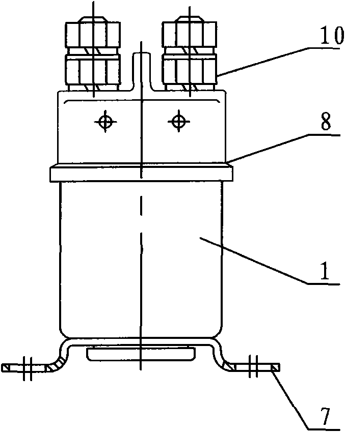
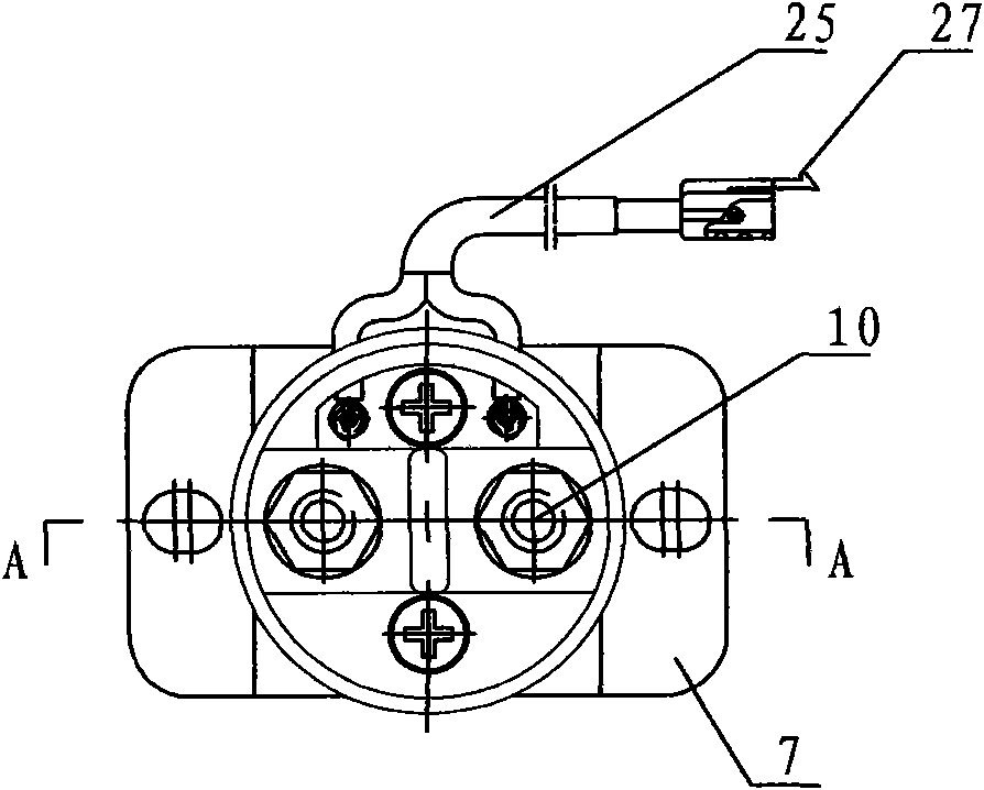
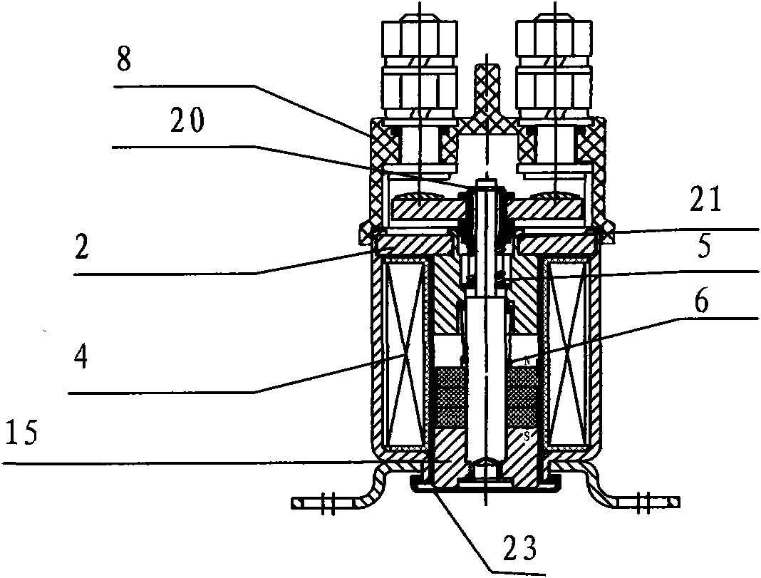
Embodiment Construction

[0026] The present invention will be further described below in conjunction with the accompanying drawings and specific embodiments, but not as a limitation of the present invention.

[0027] A preferred embodiment is given below:

[0028] Such as Figures 1 to 8 As shown, a bistable magnetic holding contactor for a power switch of an electric tricycle includes a cover assembly, the lower part of the cover assembly is connected to the shell 1, and the upper part of the shell 1 is fixed with a static iron core 2, and the static iron core 2 A moving iron core assembly is connected below, a moving contact assembly is connected above the static iron core 2, a copper sleeve 3 is arranged outside the static iron core 2, and a coil is arranged between the copper sleeve 3 and the shell 1 Assembly 4, an upper spring 5 is arranged between the static iron core 2 and the moving contact assembly, and a lower spring 6 is arranged between the static iron core 2 and the moving iron core asse...


PUM


Abstract

The invention relates to an electromagnetic switch, in particular to a bistable state magnetic latching contactor for a power supply switch of an electric tricycle. The bistable state magnetic latching contactor comprises a cover assembly, wherein the lower part of the cover assembly is connected with a casing; a static iron core is fixed on the upper part inside the casing; the lower part of thestatic iron core is connected with a movable iron core assembly; the upper part of the static iron core is connected with a movable contact assembly; a copper bush is arranged outside the static ironcore; a coil assembly is arranged between the outside of the copper bush and the casing; an upper spring is arranged between the static iron core and the movable contact assembly; and a lower spring is arranged between the static iron core and the movable iron core assembly. Compared with the prior art, the bistable state magnetic latching contactor for the power supply switch of the electric tricycle aims to eliminate the electric energy consumption and improve the performance of products and eliminates the defects that the traditional electromagnetic switch loses electric energy when being connected because a coil is always in the electrified state and the coil is easy to burn down due to long-term energization and heating.

Description

technical field [0001] The invention relates to an electromagnetic switch, in particular to a bistable magnetic holding contactor for a power switch of an electric tricycle. Background technique [0002] The original traditional electromagnetic switch is turned on and off by applying a certain excitation voltage to the coil. When the switch is in the working state (such as the switch is turned on), the coil needs to apply the excitation voltage. Only in another working state (such as the switch disconnect), the excitation voltage on the coil can be removed at this time, so as long as the switch is turned on, the coil needs to be connected to the excitation voltage all the time, it consumes energy for long-term electrification and heating, and the magnetic force (Ampere-turns) generated due to the increase of self-heating resistance (Number) decreases, reflected on the switch will cause the pressure of the switch contact to drop, resulting in unreliable switch contact; if the...

Claims


Application Information

Patent Timeline
IPC IPC(8): H01H51/01H01H50/16
Inventor 魏春旺
Owner 宁波松乐电器有限公司
Learn More