Primary/standby route equipment switching method and route equipment

A routing and device technology, applied in the field of network communication, can solve problems such as forwarding failure, increase equipment management and maintenance costs, and increase system failures, so as to avoid forwarding failure and improve the reliability of networking

Inactive Publication Date: 2010-09-22
BEIJING XINWANG RUIJIE NETWORK TECH CO LTD
View PDF2 Cites 33 Cited by
  • Summary
  • Abstract
  • Description
  • Claims
  • Application Information

AI Technical Summary

Problems solved by technology

[0009] When the VPLS network channel carrying VRRP packets between PE1 and PE2 fails, PE2 will also become the master routing device if it cannot receive the VRRP Advertisement packets from PE1. The routing information of the network segment of the VRRP interface has the same priority, and the remote PE3 device may choose the wrong route announced by the master routing device, resulting in a forwarding failure problem.
For example, after the VPLS network channel between PE1 and PE2 fails, media gateway A triggers an active / standby switchover due to the link failure of the active interface. The return data flow received from PE3 cannot be transparently transmitted to PE2, resulting in a forwarding failure
[0010] It can be seen that when network devices are connected to the IP / MPLS network through active / standby mode, the prior art requires built-in loopback boards on the active / standby routing devices to run the VPLS function, which not only increases the implementation complexity of PE devices, but also It is necessary to configure a VPLS network channel to carry VRRP notification messages, which increases the probability of system failure and increases the cost of equipment management and maintenance.
In addition, for other network devices other than media gateways, when accessing the IP / MPLS network in active and standby mode, the above problems also exist

Method used


Image

  • Primary/standby route equipment switching method and route equipment
  • Primary/standby route equipment switching method and route equipment
  • Primary/standby route equipment switching method and route equipment

Examples


Embodiment Construction

[0029] In order to make the purpose, technical solutions and advantages of the embodiments of the present invention clearer, the technical solutions in the embodiments of the present invention will be clearly and completely described below in conjunction with the drawings in the embodiments of the present invention. Obviously, the described embodiments It is a part of embodiments of the present invention, but not all embodiments. Based on the embodiments of the present invention, all other embodiments obtained by persons of ordinary skill in the art without creative efforts fall within the protection scope of the present invention.

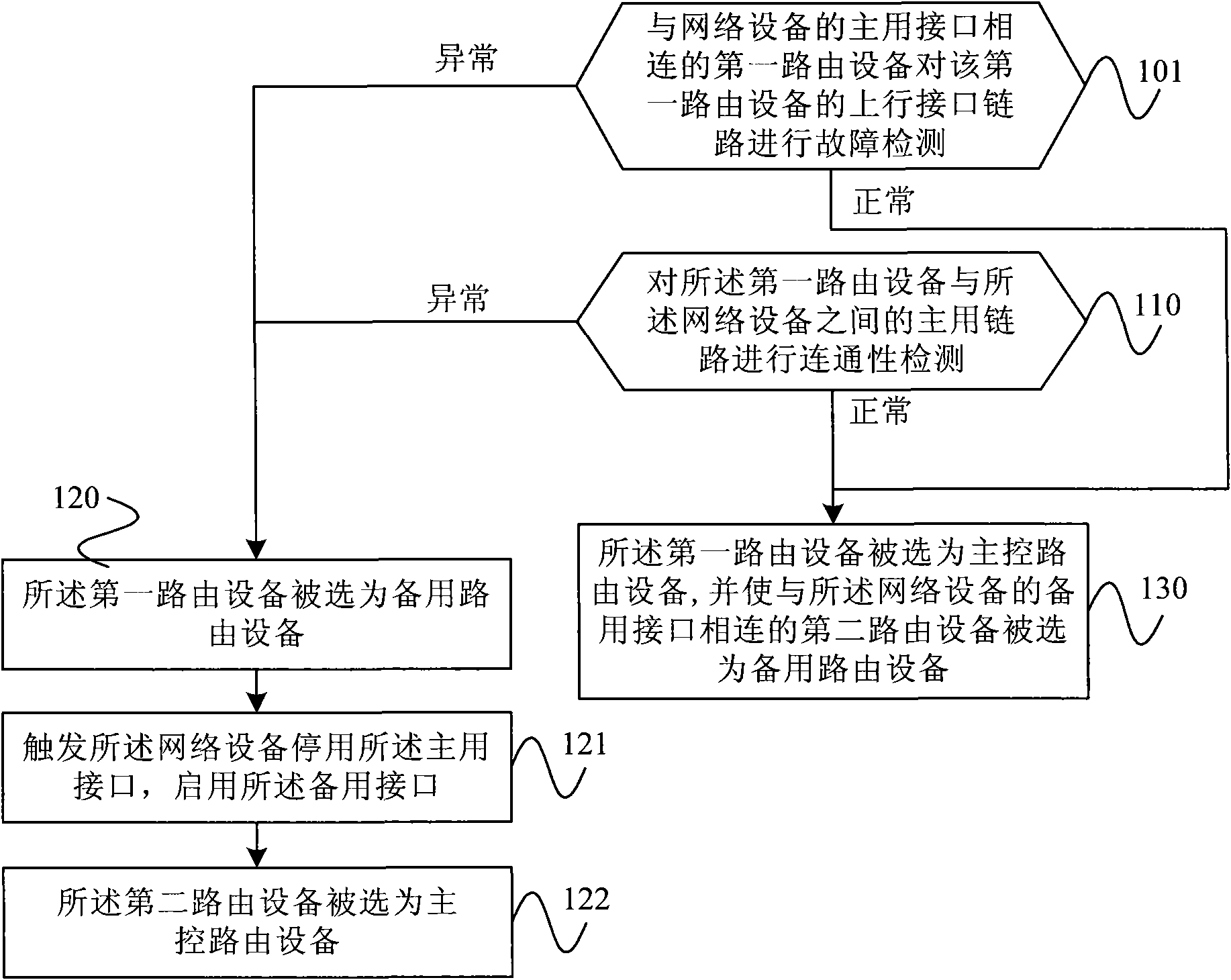
[0030] image 3 It is a flow chart of Embodiment 1 of the method for switching between active and standby routing devices according to the present invention. As shown in the figure, the method includes the following steps:

[0031] Step 101, the first routing device connected to the main interface of the network device performs fault detection on...


PUM


Abstract

The invention relates to a primary/standby route equipment switching method and route equipment. The method comprises the steps of: carrying out fault detection on an uplink interface link of the first route equipment by first route equipment connected with a primary interface of network equipment; performing connectivity detection on a primary link between the first route equipment and the network equipment; and when a detection result of the fault detection and a detection result of the connectivity detection are both normal, selecting the first route equipment as master control route equipment. Only when the fault detection result and the connectivity detection result are both normal, the route equipment connected with the primary interface of the network equipment is upgraded to be the master control route equipment, and if the fault detection result and the connectivity detection result are not normal the route equipment is degraded to be standby route equipment, so that the method avoids phenomenon of obstructed forwarding and improves the networking reliability that the network equipment accesses the IP/MPLS network in a primary/standby mode.

Description

technical field [0001] The present invention relates to the technical field of network communication, in particular to a method for switching between active and standby routing devices and routing devices. Background technique [0002] The existing transmission control protocol / Internet protocol (Transmission Control Protocol / Internet Protocol, TCP / IP for short) based network usually needs to have recovery and redundancy. Virtual Router Redundancy Protocol (Virtual Router Redundancy Protocol, referred to as: VRRP) is a protocol used to achieve router redundancy, and is used to set the default gateway (Default Gateway) for redundancy. The VRRP protocol combines multiple routing devices running the VRRP protocol (also called VRRP devices) in the system into a virtual routing device, which provides a fixed IP address and Media Access Control (Media Access Control) for terminal network devices. ; Abbreviation: MAC) address. [0003] Among the multiple VRRP devices, the one wi...

Claims


Application Information

Patent Timeline
Patent Type & Authority Applications(China)
IPC IPC(8): H04L1/22H04L12/24H04L12/26H04L12/56H04L45/24
Inventor 陈佑建
Owner BEIJING XINWANG RUIJIE NETWORK TECH CO LTD
Why Eureka
Try Eureka