AI technical title is built by Patsnap AI team. It summarizes the technical point description of the patent document.
A technology of flipping machine and flipping board, which is applied in the field of PCB manufacturing, and can solve problems such as impracticability
Inactive Publication Date: 2010-09-29
南通水山环保设备有限公司
View PDF5 Cites 37 Cited by
Summary
Abstract
Description
Claims
Application Information
AI Technical Summary
This helps you quickly interpret patents by identifying the three key elements:
Problems solved by technology
Method used
Benefits of technology
Problems solved by technology
[0003] However, the currently commonly used turning machine is a scissors-type fork frame structure. The circuit board is forked by the fork frame, and then the fork frame is horizontally rotated 180 degrees along one side of the plate, and then the plate is sent out. The machine is only equipped with a transmission mechanism, so the flip plate can only enter from the specified direction, and cannot realize
Method used
Image
Click on the blue label to locate the original text in one second.
Reading with bidirectional positioning of images and text.
Examples
Embodiment 1
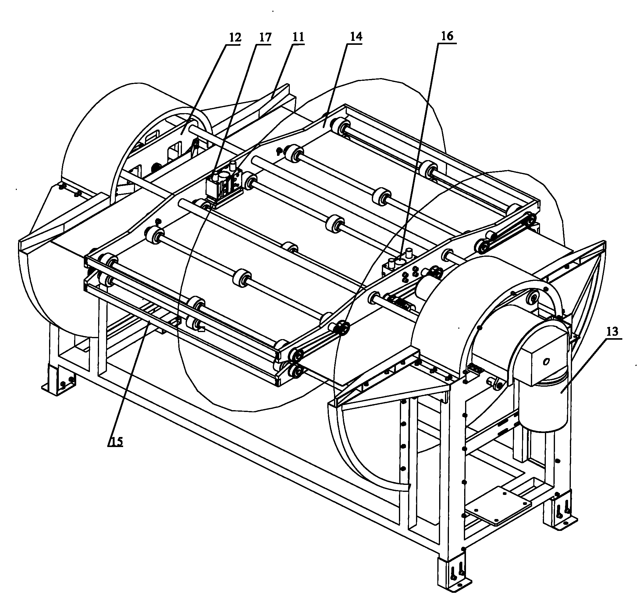
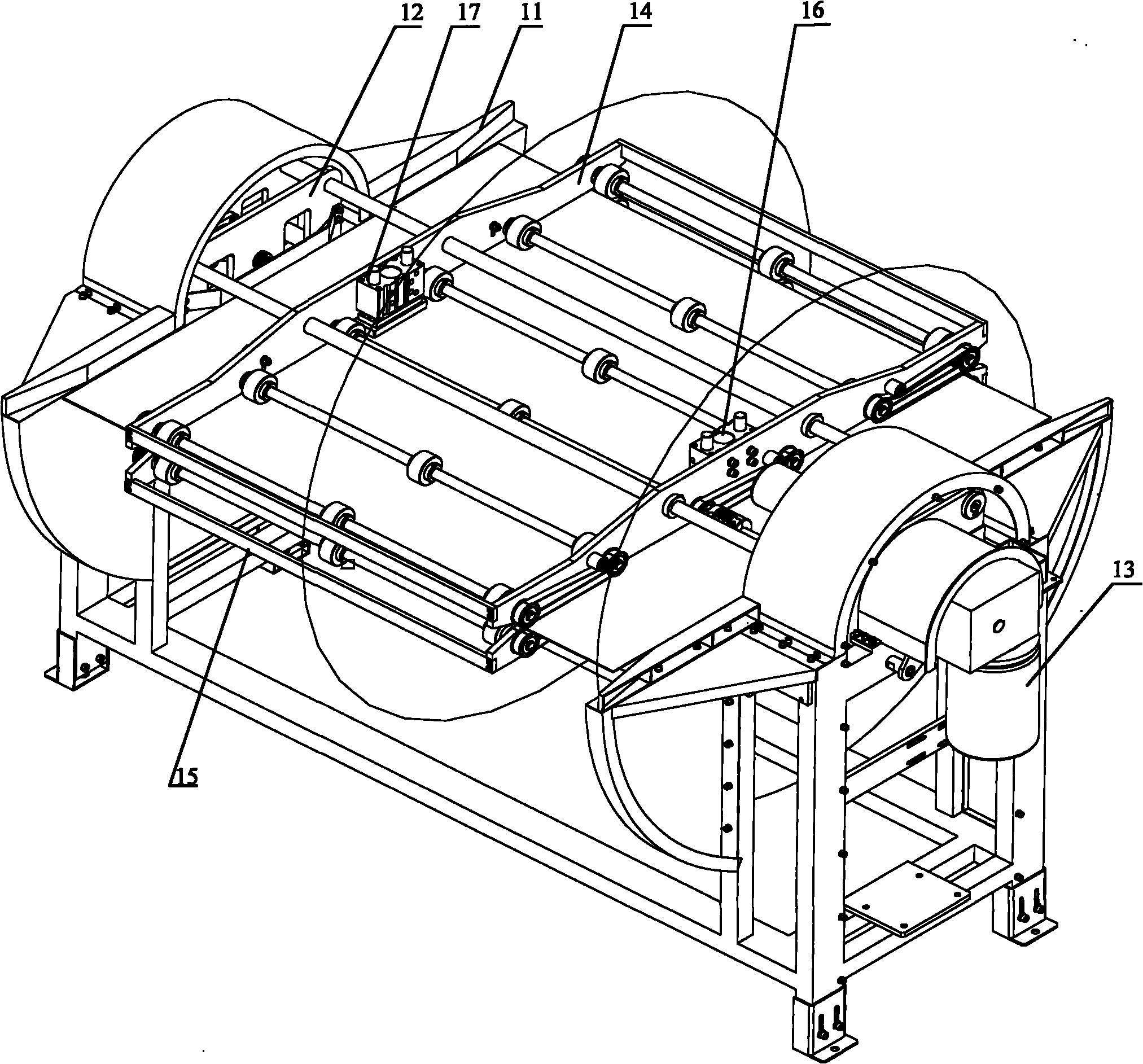
[0027] Such as figure 1 As shown, a turning machine includes: a frame 11 , a motor 13 , a mounting plate 11 , transmission components 14 and 15 and anti-falling components 17 and 16 .
[0028] The frame 11 is used to support the motor 13, the mounting plate 11, the transmission parts 14 and 15 and the anti-falling parts 17 and 16;
[0029] The motor 13 is fixed on one end of the frame 11, and the output shaft of the motor 13 is fixed with a first mounting plate (not marked in the figure), and the first mounting plate can rotate under the drive of the motor 13;
[0030] The second mounting plate 12 hinged on the other end of the frame 11 and rotates in the same direction as the motor 13;
[0031] Be installed in between described first installation board and the second installation board 12 and be used to transfer the transfer member 14 and 15 of turnover board, the distance between described transfer member 14 and 15 is greater than the thickness of transfer board; Transfer m...
Embodiment 2
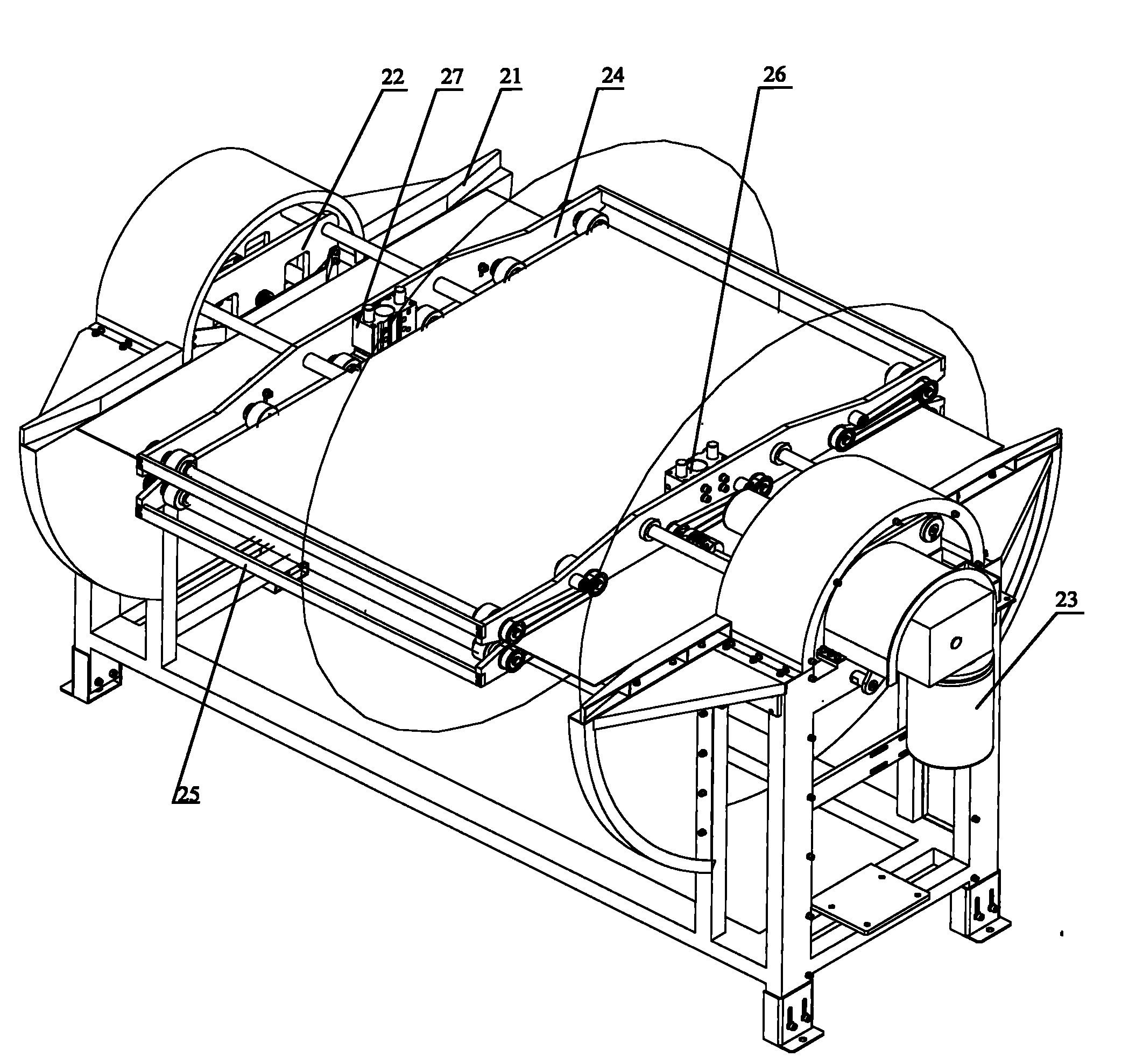
[0038] Such as figure 2 As shown, a turning machine includes: a frame 21 , a motor 23 , a mounting plate 21 , transmission components 24 and 25 and anti-falling components 27 and 26 .
[0039] The frame 21 is used to support the motor 23, the mounting plate 21, the transmission parts 24 and 25 and the anti-falling parts 27 and 26;
[0040] The motor 23 is fixed on one end of the frame 21, and the output shaft of the motor 23 is fixed with a first mounting plate (not marked in the figure), and the first mounting plate can rotate under the drive of the motor 23;
[0041] The second mounting plate 22 hinged on the other end of the frame 21 and rotates in the same direction as the motor 23;
[0042] Be installed in between described first mounting plate and the second mounting plate 22 and be used for transmitting the transmission parts 24 and 25 of flipping board, the distance between described transmission parts 24 and 25 is greater than the thickness of flipping board; Transm...
PUM
Abstract
The embodiment of the invention discloses a panel turnover machine which comprises a stand, a motor, a first mounting panel, a second mounting panel, a first transmission component, a second transmission component and an anti-falling component, wherein the motor is fixed at one end of the stand; the first mounting panel is fixed on an output shaft of the motor; the second mounting panel is articulated on the other end of the stand and rotates in the same direction as the rotary motor; the first transmission component and the second transmission component are arranged between the first mounting panel and the second mounting panel and used for transmitting a turnover panel, and the distance between the first transmission component and the second transmission component is larger than the thickness of the turnover panel; and the anti-falling component for preventing the turnover panel from falling off is arranged between the first transmission component and the second transmission component. It can be seen from the technical scheme that because the two transmission components are arranged between the first mounting panel and the second panel, when the turnover panel is transmitted to a specified position by the first turnover panel and when the motor drives the first mounting panel and the second mounting panel to turn over 180 degrees, the turnover panel and the two transmission components simultaneously turn over.
Description
technical field [0001] The invention relates to the field of PCB manufacturing, more specifically, to a two-way in and out turning machine. Background technique [0002] PCB (Printed Circuit Board, printed circuit board) is a support for electronic components and a provider of electrical connections for electronic components. In the PCB manufacturing industry, PCB finished products, semi-finished products or tooling require double-sided processing in many processes (such as flattening the production line, grindingproduction line, etc.), but only one side of the circuit board can be processed in any production line at a time, so a turning machine is needed After processing one side, turn the board horizontally 180 degrees to process the other side. The turning machine is a common turning device. [0003] However, the currently commonly used turning machine is a scissors-type fork frame structure. The circuit board is forked by the fork frame, and then the fork frame is hori...
Claims
Application Information
Patent Timeline
Application Date:The date an application was filed.
Publication Date:The date a patent or application was officially published.
First Publication Date:The earliest publication date of a patent with the same application number.
Issue Date:Publication date of the patent grant document.
PCT Entry Date:The Entry date of PCT National Phase.
Estimated Expiry Date:The statutory expiry date of a patent right according to the Patent Law, and it is the longest term of protection that the patent right can achieve without the termination of the patent right due to other reasons(Term extension factor has been taken into account ).
Invalid Date:Actual expiry date is based on effective date or publication date of legal transaction data of invalid patent.

