
Sewing machine

A sewing machine and support mechanism technology, applied in the field of sewing machines, can solve problems such as difficulty in adjusting oil supply

Active Publication Date: 2010-09-29
BROTHER KOGYO KK
View PDF4 Cites 1 Cited by
  • Summary
  • Abstract
  • Description
  • Claims
  • Application Information

AI Technical Summary

Problems solved by technology

In the oil supply device of the sewing machine described in the above-mentioned patent publication, it is difficult to adjust the oil supply amount.

Method used


Image

  • Sewing machine
  • Sewing machine
  • Sewing machine

Examples


Embodiment Construction

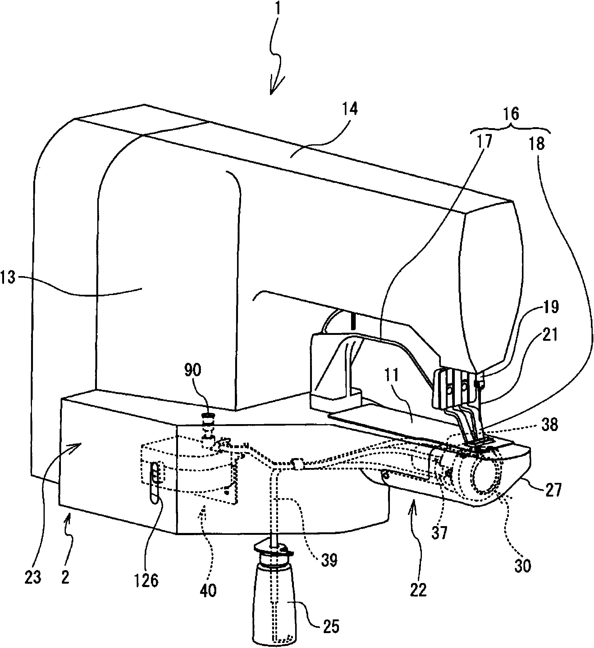
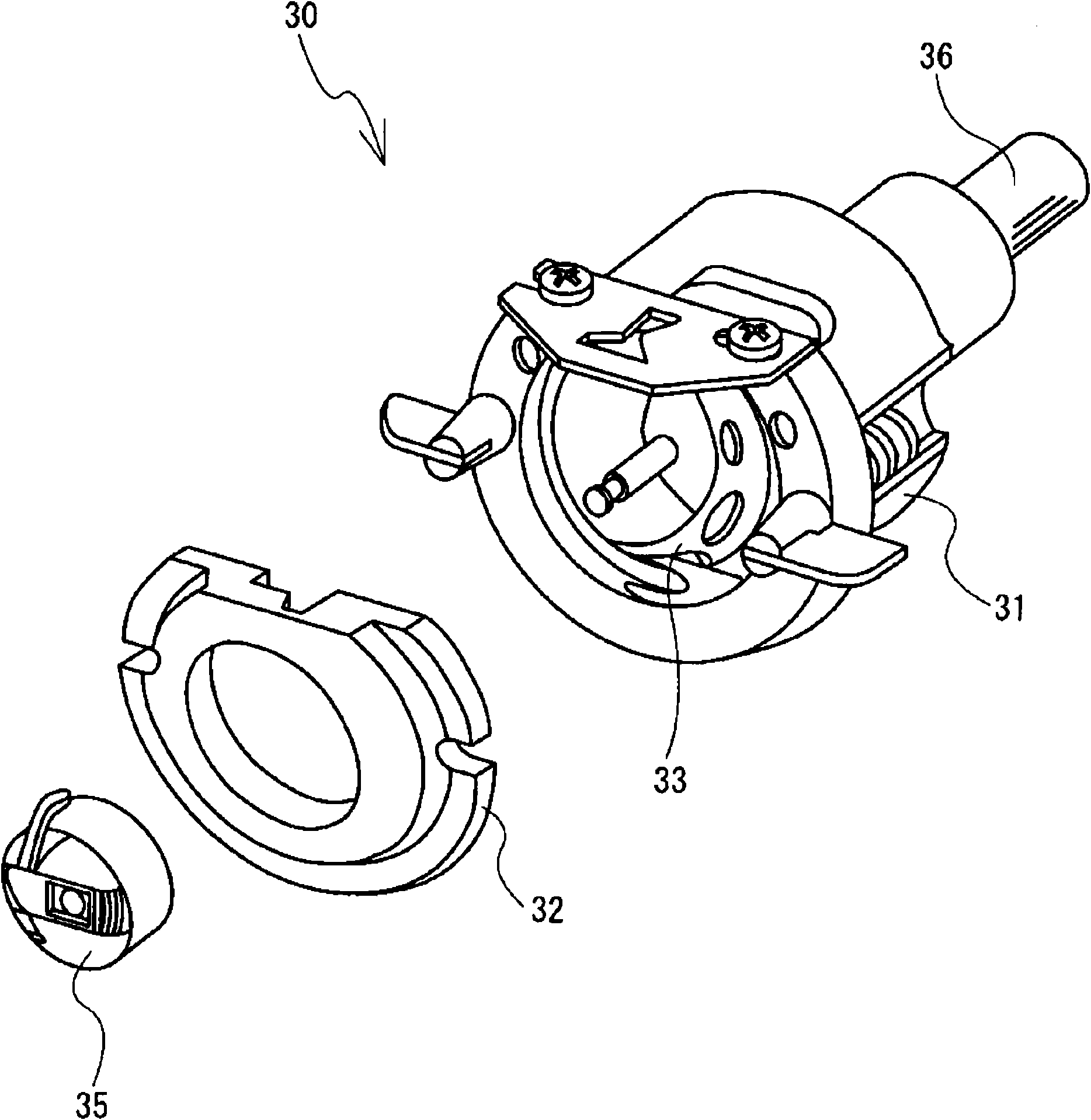
[0041] Next, a sewing machine 1 according to an embodiment of the present invention will be described with reference to the drawings. refer to figure 1 , the structure of the sewing machine 1 will be described. Will figure 1 Right obliquely lower, left obliquely upper, right obliquely upper, left obliquely lower as the front, rear, right and left of the sewing machine 1 respectively.

[0042]The sewing machine 1 includes a base 2 , a substantially square pillar-shaped column portion 13 , and a substantially square pillar-shaped machine arm portion 14 . The column portion 13 extends upward from the rear of the base 2 . The arm portion 14 extends forward from the upper portion of the column portion 13 . The arm part 14 includes a needle bar 19 in its lower part. The needle bar 19 is driven to reciprocate up and down by a motor (not shown). The needle bar 19 includes a needle 21 at its lower end. A thread spool (not shown) supplies the upper thread to the needle 21 .

[0...


PUM


Abstract

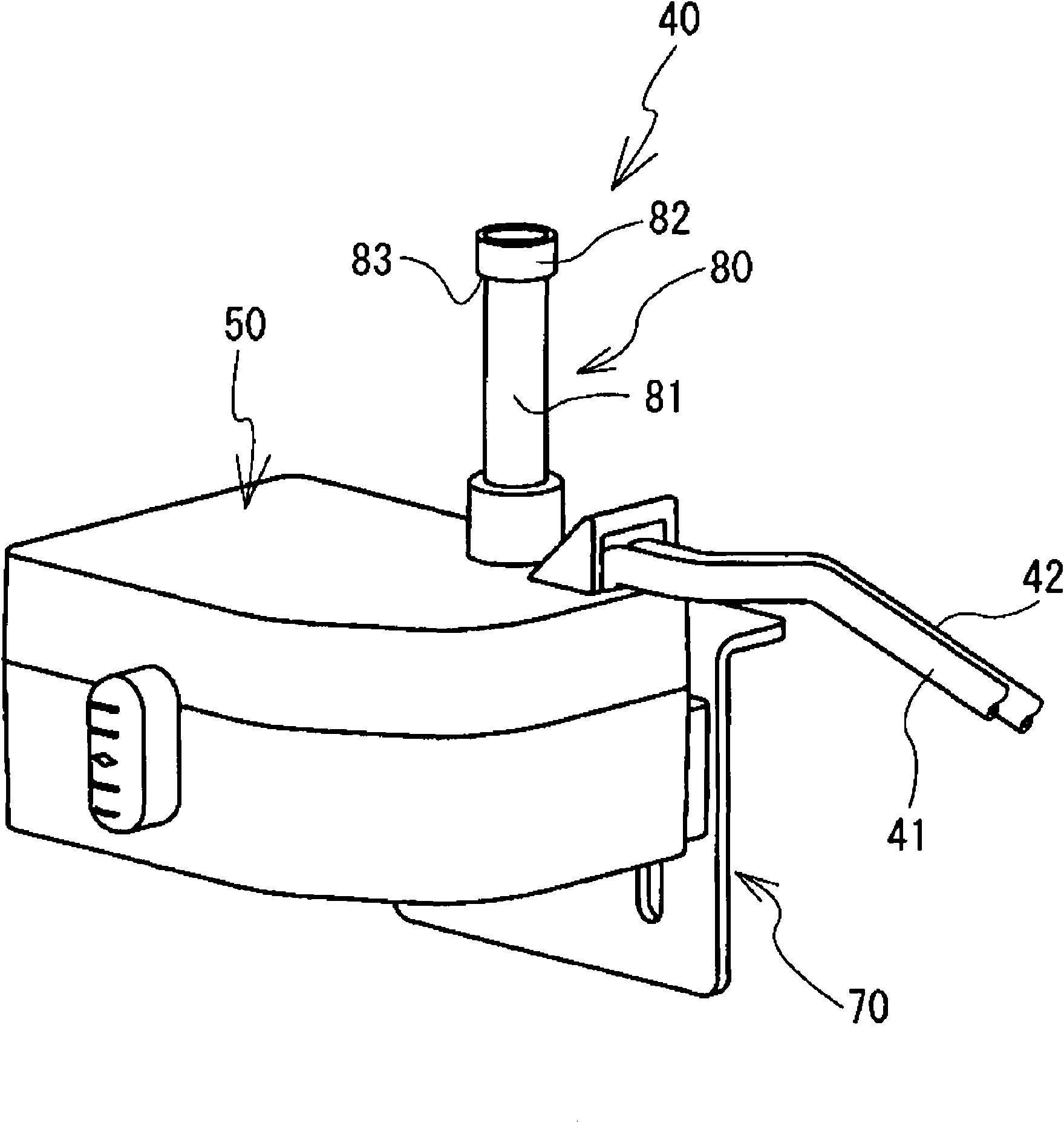
The invention relates to a sewing machine capable of easily adjusting the supply amount of a lubricating oil to a shuttle mechanism. The lubricating oil is stored in a fuel tank. The lubricating oil in the fuel tank is guided to a lubricating oil feeding opening of the shuttle mechanism by an oil core based on the capillary phenomenon. A support mechanism supports the fuel tank to move up and down relative to the shuttle mechanism. The supply amount of the lubricating oil to the shuttle mechanism is dependent on the height difference of the shuttle mechanism and the fuel tank. An operator changes the up-and-down position of the fuel tank to adjust the supply amount of the lubricating oil to the shuttle mechanism. The operator can easily adjust the upply amount of the lubricating oil to the shuttle mechanism.

Description

technical field [0001] The present invention relates to a sewing machine including an oil tank storing lubricating oil supplied to a shuttle mechanism. Background technique [0002] Conventionally, a sewing machine includes a shuttle mechanism in a base portion thereof. Sewing machines need to supply lubricating oil to the shuttle mechanism. The oil supply device of the sewing machine described in Japanese Patent Laid-Open No. 9875 of 1999 includes an oil reservoir and an oil wick. The oil reservoir stores oil. The oil wick supplies the oil stored in the oil reservoir to the shuttle mechanism, etc. by capillary action. In the oil supply device described in the aforementioned patent publication, one end of the oil wick is immersed in the oil in the oil reservoir. The other end of the oil wick is in contact with the shuttle mechanism or the like. The oil goes through the oil wick to the shuttle mechanism etc. [0003] In the oil supply device for sewing machines describe...

Claims


Application Information

Patent Timeline
IPC IPC(8): D05B71/02
Inventor 和田哲也中村英彦
Owner BROTHER KOGYO KK
Learn More