Electromagnetic water inlet valve

A water inlet valve, electromagnetic technology, applied in the field of electromagnetic valve, can solve the problem of small flow, unable to discharge water, etc., to achieve the effect of increasing the flow

Active Publication Date: 2012-05-23
HANGZHOU KAMBAYASHI ELECTRONICS
View PDF3 Cites 1 Cited by
  • Summary
  • Abstract
  • Description
  • Claims
  • Application Information

AI Technical Summary

Problems solved by technology

[0018] The present invention aims to solve the problem that the electromagnetic water supply valve in the prior art has a relatively small flow rate in the range of low water pressure (0.01Mpa~0.03Mpa) so that water cannot flow out. Therefore, an electromagnetic water inlet valve of the present invention is provided.

Method used


Image

  • Electromagnetic water inlet valve
  • Electromagnetic water inlet valve
  • Electromagnetic water inlet valve

Examples


Embodiment 1

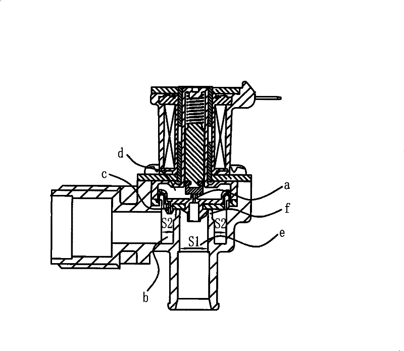
[0058] The electromagnetic water inlet valve of the present embodiment, see Figure 4 , Figure 5 , Figure 6a , Figure 6b , including a valve body 1, the valve body 1 is provided with a water supply chamber 101 and a water outlet chamber 102, there is a valve seat 103 between the water supply chamber 101 and the water outlet chamber 102, the valve seat 103 is matched with a diaphragm 2, and the center of the diaphragm 2 has a perforation 201 Embedded in the matching groove 301 of the diaphragm plate 3, the valve body 1 is provided with a conduit 4, and the radially outwardly expanded lower end 401 of the conduit 4 is pressed against the sealing portion 202 on the periphery of the diaphragm 2 to form a back pressure chamber 104. The center of the diaphragm plate 3 A guide hole 302 is opened at the top, and a side flow channel 303 is opened on the periphery. The water supply chamber 101 communicates with the back pressure chamber 104 through the side flow channel 303. An ele...

Embodiment 2

[0065] The electromagnetic water inlet valve of the present embodiment, see Figure 9 The difference between this embodiment and the first embodiment is that the diaphragm plate 3 is formed by a combination of the diaphragm A31 and the diaphragm B32, and the water inlet 3201 on the diaphragm B32 is formed by fitting the diaphragm A31 and the diaphragm B32. The pressure loss chamber 33 and the back pressure chamber inlet 3101 on the partition A31 constitute the side flow channel 303 .

[0066] Compared with the first embodiment, the manufacturing process of this embodiment is different due to the difference in the structure of the diaphragm plate. In practice, the user can make a choice according to the needs.

Embodiment 3

[0068] The electromagnetic water inlet valve of the present embodiment, see Figure 10There are one or several protrusions 34 on the outer periphery of the diaphragm plate 3, and there are fitting grooves 3401 on the protrusions, and the outer periphery of the diaphragm 2 also has corresponding holes 203, and the fitting grooves 3401 embedded in the hole 203. Other structures are the same as in Embodiment 1.


PUM


Abstract

The invention discloses an electromagnetic water inlet valve capable of solving the problem that the normal work cannot be carried out due to excessively-low pressure. The electromagnetic water inlet valve comprises a valve body and a valve seat arranged in the valve body, wherein the valve body is provided with a conduit; a piston is arranged in the conduit; the head part of the piston is connected with a piston nut; a convex part is arranged at one end of the piston corresponding to the valve seat; the piston nut is arranged at the convex part; a diaphragm plate has a connecting structure which is provided with a moving space and a top buckle edge of the piston convex part; the piston convex part is positioned in the moving space; the axial length of the piston convex part is less than that of the moving space, so that the piston convex part is hooked with the top buckle edge of the connecting structure after moving towards the direction away from the valve seat for a stroke in the moving space; and the piston convex part continuously moves to drive the diaphragm plate and a diaphragm together to move towards the direction away from the valve seat. The invention is suitable for a water inlet valve of a washing machine and other home appliances.

Description

technical field [0001] The invention relates to an electromagnetic valve, in particular to an electromagnetic water inlet valve assembled in household appliances. Background technique [0002] In the past, the structure of the guided electromagnetic water supply valve is that in the valve body composed of the inlet, the water supply chamber, the valve seat, the outflow chamber and the outlet, a diaphragm and a diaphragm plate for closing the valve seat (the diaphragm is attached to the diaphragm plate, two These are used together as the disc to close the valve seat), and there is also a conduit, which is equipped with a piston made of magnetically conductive material, a piston cap connected to the front end of the piston, a spring on the rear end of the piston, and an electromagnetic coil on the periphery of the conduit , the central protrusion of the diaphragm plate is provided with a guide hole corresponding to the piston cap, and the electromagnetic coil is energized and ...

Claims


Application Information

Patent Timeline
Patent Type & Authority Patents(China)
IPC IPC(8): F16K31/06F16K7/17
Inventor 王华陈国秀
Owner HANGZHOU KAMBAYASHI ELECTRONICS
Why Eureka
Try Eureka