LED lamp control circuit and LED lamp

A technology for LED lamps and control circuits, applied in the field of lighting, can solve problems such as power consumption of single-chip microcomputers, and achieve the effects of less power and less conduction voltage drop.

Active Publication Date: 2010-09-29
OCEANS KING LIGHTING SCI&TECH CO LTD +1
View PDF3 Cites 22 Cited by
  • Summary
  • Abstract
  • Description
  • Claims
  • Application Information

AI Technical Summary

Problems solved by technology

[0003] The technical problem to be solved by the present invention is to provide a power-saving LED lamp control circuit and LED lamp for the above-mentioned defects in the prior art that the single-chip microcomputer also needs battery power supply when the LED light source is in the extinguished state, thereby causing unnecessary power consumption.

Method used


Image

  • LED lamp control circuit and LED lamp
  • LED lamp control circuit and LED lamp
  • LED lamp control circuit and LED lamp

Examples


Embodiment Construction

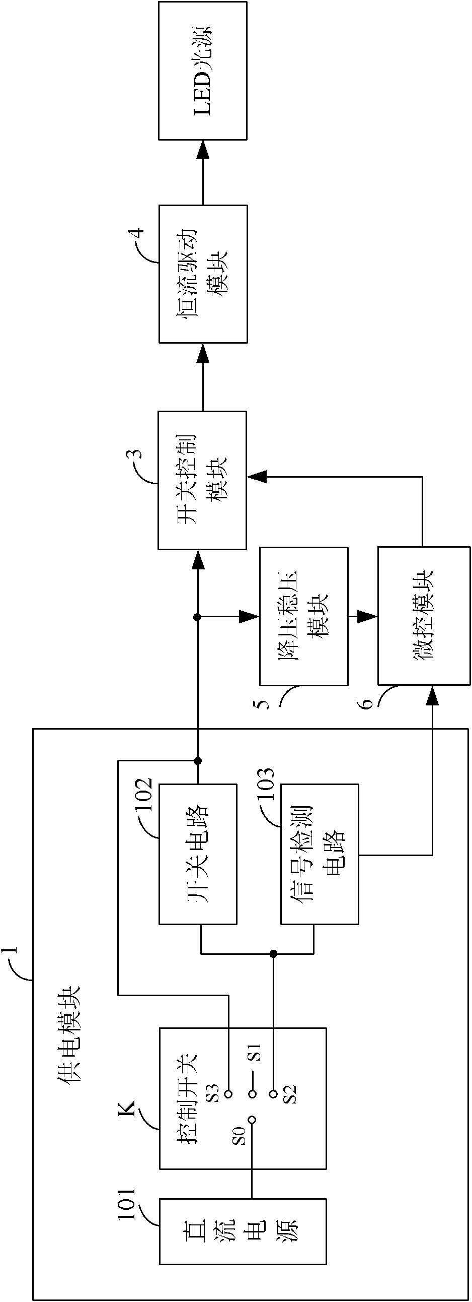
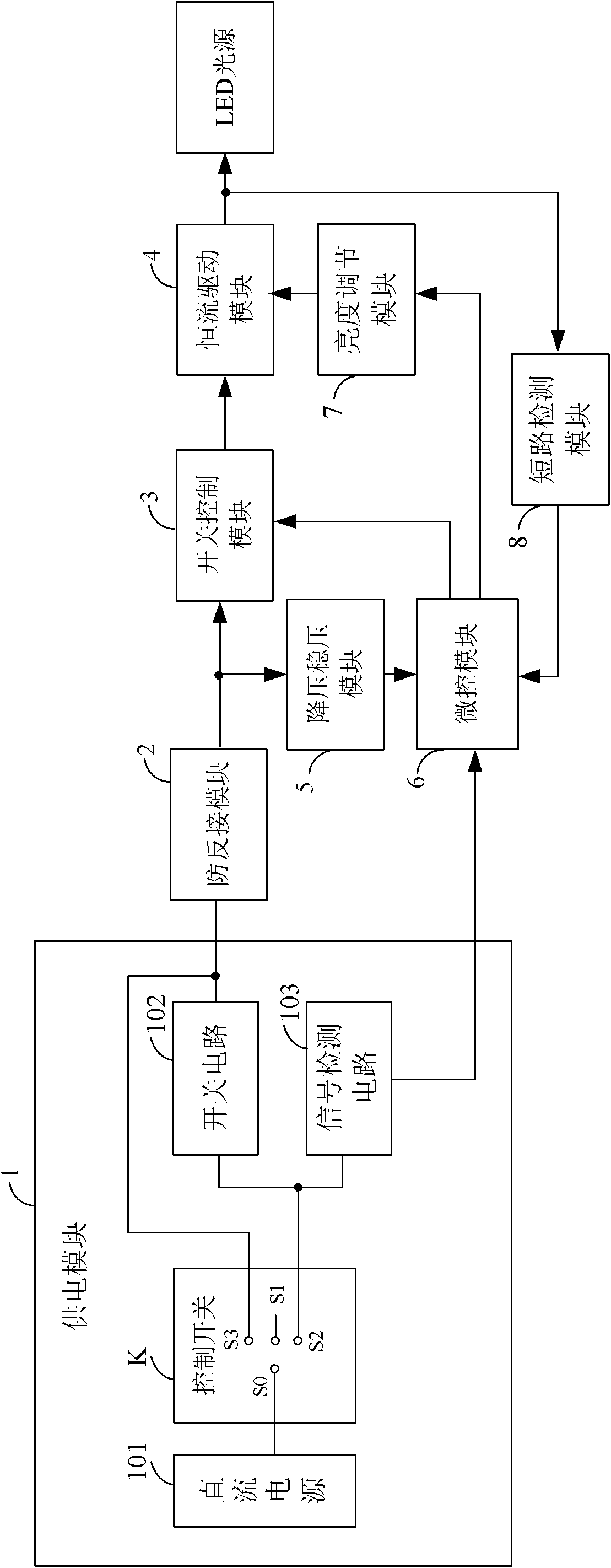
[0024] Such as figure 1 Shown is a functional block diagram of the first preferred embodiment of the LED lamp control circuit of the present invention. The LED lamp control circuit of the present invention is connected with the LED light source, and includes a power supply module 1 , a switch control module 3 , a constant current drive module 4 , a step-down and voltage stabilization module 5 and a micro-control module 6 . Among them, the power supply module 1, the switch control module 3 and the constant current drive module 4 are connected in sequence, the power supply module 1 supplies power to the constant current drive module 4 after passing through the switch control module 3, and the step-down and voltage stabilization module 5 controls the voltage provided by the power supply module 1. The step-down and voltage stabilization process supplies power to the micro-control module 6 , and the micro-control module 6 controls the working state of the switch control module 3 . ...


PUM


Abstract

The invention relates to an LED lamp control circuit and an LED lamp. The LED lamp control circuit comprises a power supply module, a switch control module, a constant current driving module, a voltage drop and stabilization module and a micro-control module, The power supply module comprises a direct current power supply, a control switch, a switch circuit and a signal detection circuit, whereinthe control switch is used for controlling the direct current power supply to switch on or switch off, the switch circuit is switched on or switched off according to electrical signals on the controlswitch, and the signal detection circuit generates a detection signal according to the electrical signals on the control switch. The micro-control module controls the switch module to generate a first output voltage or the second output voltage according to the detection signals. The constant current driving module generates a first constant current or a second constant current according to the first output voltage or the second output voltage so that an LED light source works in a high light mode or a low light mode. In the invention, when the LED light source is extinguished, the direct current power supply does not need to supply power for the micro-control module, thereby the electric quantity is saved, and the LED light source can be switched between the high light mode and the low light weight.

Description

technical field [0001] The invention relates to the technical field of lighting, and more specifically, to an LED lamp control circuit and an LED lamp. Background technique [0002] In the prior art, the LED light source has the advantages of high efficiency and energy saving, long life, low voltage controllability, etc., so it is widely used in various lamps. Mobile LED lamps are generally powered by batteries. In the existing LED lamp control circuit, the control switch is set between the single-chip microcomputer and the ground. The single-chip microcomputer generates a square wave signal by detecting the operation state of the control switch. The square wave signal controls The constant current driving circuit generates a constant current to supply power for the LED light source. The single-chip microcomputer can also control the LED light source to turn off by detecting the action state of the control switch. When the LED light source is in the extinguished state, the...

Claims


Application Information

Patent Timeline
Patent Type & Authority Applications(China)
IPC IPC(8): H05B37/02F21S2/00F21V23/00F21Y101/02
Inventor 周明杰王学军
Owner OCEANS KING LIGHTING SCI&TECH CO LTD
Why Eureka
Try Eureka