Elevator door device
A door device and elevator technology, applied in the field of elevator door devices, can solve problems such as increased production cost and the like
- Summary
- Abstract
- Description
- Claims
- Application Information
AI Technical Summary
Problems solved by technology
Method used
Image

Examples
Embodiment approach 1
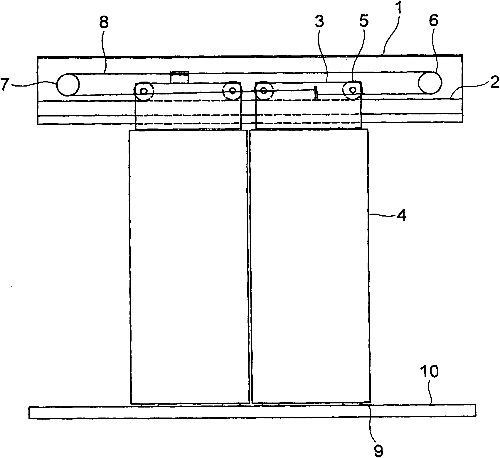
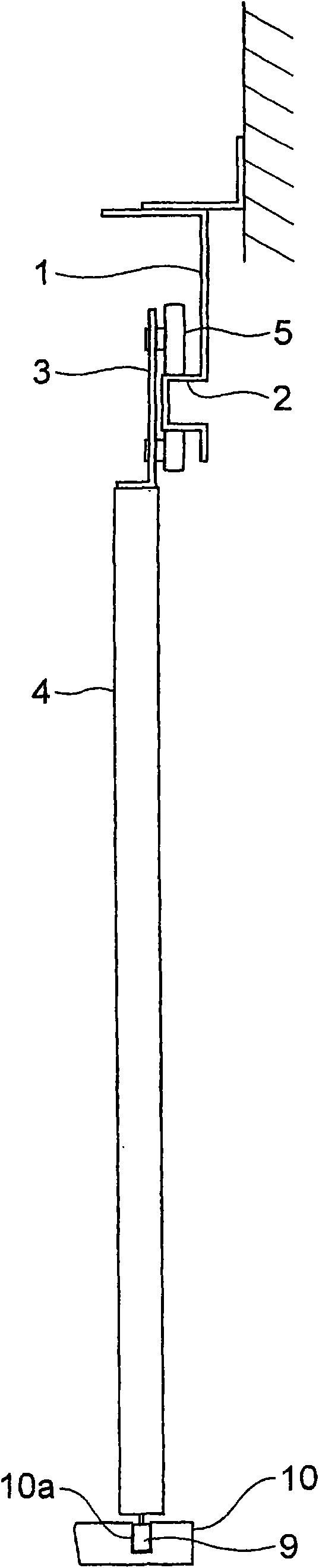
[0022] figure 1 It is a front view showing the door apparatus of an elevator according to Embodiment 1 of the present invention, and is a view of the landing door apparatus viewed from the hoistway side. and, figure 2 yes means figure 1 Side view of the gate mechanism in . A hanger case (hanger case) 1 is fixed above the landing entrance. A hanger rail 2 is provided in the hanger housing 1 . A pair of door panels 4 are suspended on the hanging door track 2 via a pair of door hangers 3 . The landing entrance and exit are opened and closed through the door panel 4 .
[0023] The door hanger 3 is fixed on the upper end of the door panel 4 . Each door hanger 3 is provided with a plurality of hanger rollers 5 that roll along the door rail 2 .
[0024] An interlocking wheel 6 is provided near one end in the longitudinal direction of the hanger case 1 , and an interlocking wheel 7 is provided near the other end in the longitudinal direction of the hanger case 1 . A cable 8 i...
Embodiment approach 2
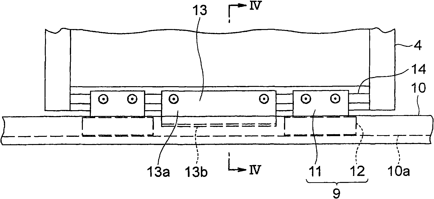
[0034] Next, Figure 5 It is a sectional view of main parts of an elevator door apparatus according to Embodiment 2 of the present invention. In the drawing, the engaging groove 10b is provided at the lower end portion of the side wall in the sill groove 10a. An upper groove 10c is provided on the upper surface (top surface) inside the engagement groove 10b.
[0035] At the front end portion of the engaging portion 13b of the hook fitting 13, a folded portion 13c bent upward at a right angle is provided. The folded portion 13c protrudes upward from the front end portion of the engaging portion 13b and is inserted into the upper groove 10c. And, when the door panel 4 performs an opening and closing operation, the folded portion 13c moves in the upper groove 10c. Other configurations are the same as those in Embodiment 1.
[0036] In such an elevator door device, since the upper groove 10c is provided in the engaging groove 10b and the turning part 13c is provided on the hoo...
Embodiment approach 3
[0038] Next, Figure 6 It is a sectional view of main parts of an elevator door device according to Embodiment 3 of the present invention, Figure 7 yes means Figure 6 A perspective view of the guide body in . In the figure, the guide body 15 has: a guide body mounting fitting 16 with an L-shaped cross section, which is installed on the door panel 4 and also serves as a hooking fitting; and a guide shoe 12, which is fixed on the guide body mounting fitting 16, and Inserted into the sill groove 10a.
[0039]The guide mounting bracket 16 has a vertical mounting portion 16a and an engaging portion 16b formed by bending the lower end portion of the mounting portion 16a at a right angle. The upper end portion of the mounting portion 16 a is mounted on the door panel 4 . The lower end portion of the mounting portion 16 a is embedded in the guide shoe 12 . The engaging portion 16b protrudes horizontally from the side surface of the guide shoe 12 and is inserted into the engagin...
PUM
 Abstract
Description
Claims
Application Information