Multi-plate frictional element

A friction element and component technology, applied in the field of multi-plate friction elements, can solve problems such as inapplicability

Inactive Publication Date: 2010-10-06
JATCO LTD
View PDF5 Cites 11 Cited by
  • Summary
  • Abstract
  • Description
  • Claims
  • Application Information

AI Technical Summary

Problems solved by technology

Therefore, in consideration of hydraulic controllability, for example, it cannot be applied when the connection capacity is extremely small such as 1 / 10 of the connection capacity ratio.

Method used


Image

  • Multi-plate frictional element
  • Multi-plate frictional element
  • Multi-plate frictional element

Examples


Embodiment Construction

[0059] Embodiments of the present invention will be described below based on the drawings.

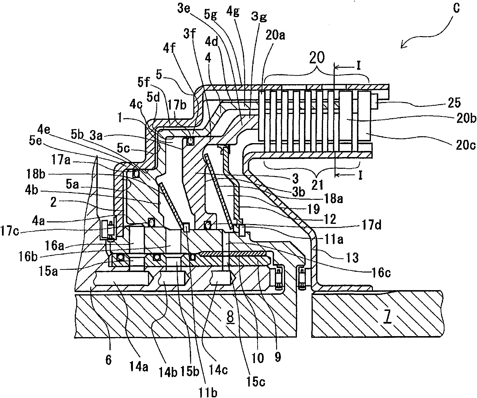
[0060] The clutch of the present embodiment is a so-called tandem piston type wet multi-plate clutch, and is engaged at shift stages having different engagement capacities such as the first speed and the fourth speed.

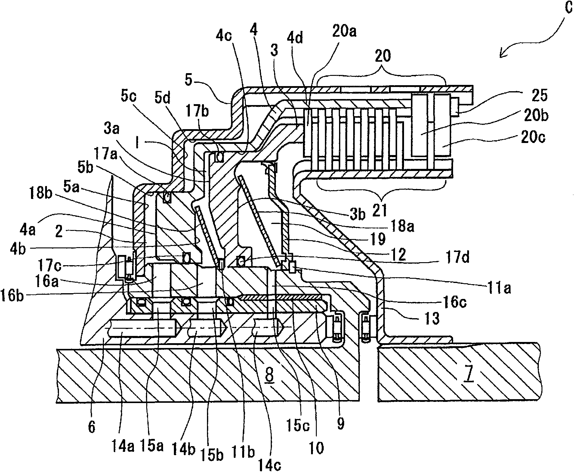
[0061] figure 1 , figure 2 is a sectional view of a clutch as a friction element of the first embodiment, figure 1 Indicates the connection state when the connection capacity is large, figure 2 Indicates the join status when the join capacity is low.

[0062] Also, in the following description, the figure 1 Use the left side as the front and the right side as the rear.

[0063] The clutch C is engaged to transmit power from the input rotary shaft 8 connected to the drive source side to the output shaft 7 connected to the wheel side.

[0064] Both the first piston 3 and the second piston 4 are accommodated in the clutch drum 5 so that the radially inner side ther...


PUM


Abstract

The invention provides a multi-plate frictional element which can deal with a larger connection capacity ratio without reducing the control performance. The multi-plate frictional element includes: a plurality of first plate members (20) which are slidably locked with a first locking portion of a first member (5); a plurality of second plate members (21) which are slidably locked with a second locking portion of a second member (13) and concentrically alternately arranged with the second plate members (21) to form a plate member row; first link devices (1, 3) which link plural first plate members (20) and plural second plate members (21); second link devices (2, 4) which link a part of plural first plate members (20) and a part of plural second plate members (21); and power is transmitted between the first member (5) and the second member (13) through selectively driving the first link devices (1, 3) or the second link devices (2, 4) to act.

Description

technical field [0001] This invention relates to multi-plate friction elements for automatic transmissions and the like. Background technique [0002] In an automatic transmission, hydraulically actuated multi-plate friction elements such as clutches and brakes are used, and these are switched between engagement and release in accordance with a gear stage. At this time, for example, one friction element may be engaged at a plurality of different shift stages such that the second and third speeds are released and the first and fourth speeds are engaged. [0003] In such a case, the engagement capacity of the friction elements differs depending on the engaged gear stage. In addition, the smaller the ratio of the engagement capacities of the transmission stages, that is, the smaller the engagement capacity ratio, the worse the hydraulic controllability. In addition, the engagement capacity ratio is the engagement capacity at the shift stage with the smaller engagement capacit...

Claims


Application Information

Patent Timeline
Patent Type & Authority Applications(China)
IPC IPC(8): F16D25/0638
CPCF16D25/02F16D25/063F16D25/0638
Inventor 山下胜则小栗和夫
Owner JATCO LTD
Why Eureka
Try Eureka