Magnetic force-limiting device and vertebral body traction bed using same

A magnet and magnetic force technology, applied in the field of tension protection devices, can solve problems such as endangering personal safety and prone to accidents, and achieve the effect of ensuring human safety and ensuring safety

Inactive Publication Date: 2015-08-19
何少敦
View PDF9 Cites 0 Cited by
  • Summary
  • Abstract
  • Description
  • Claims
  • Application Information

AI Technical Summary

Problems solved by technology

[0004] In order to solve the problem that the operation or stop of the control driving device in the current traction equipment is performed by electrical switches or electronic components, when the electrical switches or electronic components fail, or when manual operation is wrong, it is easy to cause accidents and endanger personal safety. , the present invention proposes a magnetic force limiting device. The magnet and the tension member are magnetically attracted together to form a tension connection assembly. The tension member is provided with a force point, and the tension force is applied to the tension connection assembly through the force point. When the pulling force reaches the resultant force of magnetic attraction, the pulling force connection components that are attracted together are separated to release the pulling force, and finally play a protective role

Method used


Image

  • Magnetic force-limiting device and vertebral body traction bed using same
  • Magnetic force-limiting device and vertebral body traction bed using same
  • Magnetic force-limiting device and vertebral body traction bed using same

Examples


Embodiment Construction

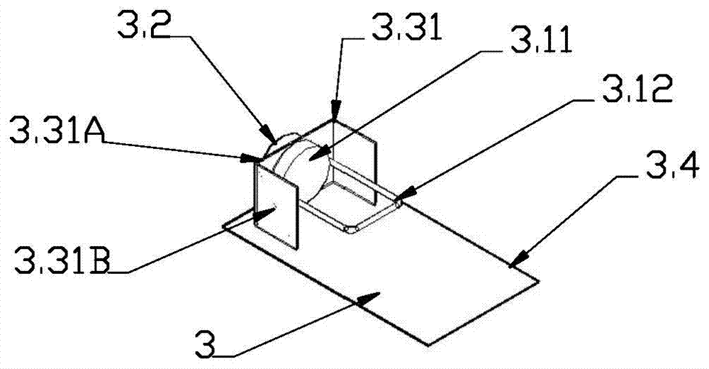
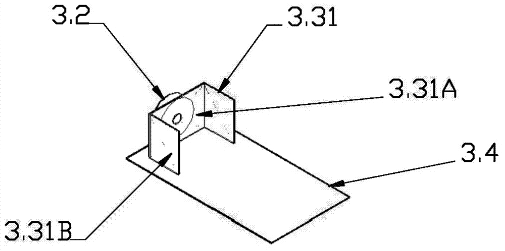
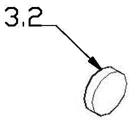
[0029] figure 1 , figure 2 , image 3 , Figure 4 It is an enlarged schematic diagram of the structure of the first embodiment of the magnetic force limiting device, wherein figure 2 , image 3 , Figure 4 It is a schematic diagram of the local structure. As shown in the figure, in this example, the magnetic force limiting device 3 includes a magnet 3.2, a tension member 3.1, a first fixed seat 3.31, and a base 3.4. The tension member 3.1 is composed of a suction member 3.11 and a hook 3.12. It is a magnetic body, and the first fixed seat is bent to form a groove-shaped structure by bending a metal plate. The first fixed seat 3.31 has a middle flat seat 3.31A and two bent feet 3.31B. The first fixed seat 3.31 is horizontally installed and fixed on the base 3.4 Above, the magnet 3.2 is fixed on one side of the flat seat 3.31A of the first fixed seat and the tension member 3.1 is arranged on the other side of the flat seat 3.31A. The flat seats 3.31A are spaced apart an...


PUM


Abstract

A magnetic force limiter (3) and vertebral body traction bed thereof; the magnetic force limiter (3) comprises a magnet (3.2), a tensioning piece (3.1), a first fixed seat (3.31) and a base (3.4); the tensioning piece (3.1) is comprised of an attraction piece (3.11) and a hook (3.12); the first fixed seat (3.31) is a magnetic body, and is a groove-shaped structure formed by bending a metal plate; the first fixed seat (3.31) has a middle flat seat (3.31A) and two bent end feet (3.31B); the first fixed seat (3.31) is horizontally installed and fixed on the base (3.4); the magnet (3.2) is fixed on one side of the flat seat (3.31A) of the first fixed seat (3.31), and the tensioning piece (3.1) is disposed at the other side of the flat seat (3.31A); the magnet (3.2) and the attraction piece (3.11) are separated by the flat seat (3.31A), and are attracted via magnetic force to form a tension connecting assembly; external tension is applied on the tension connecting assembly via the hook (3.12); and when the tension reaches the magnetic attraction force, the tension connecting assembly will separate to release the tension. The vertebral body traction bed employing the magnetic force limiting device (3) comprises a bed body (1), an electric drive device (2) and a pulling belt device (4); the electric drive device (2) is disposed at the lower side of a bed board (1.1); the magnetic force limiting device (3) is connected in tandem with the pulling belt device (4), and the magnetic attraction force of the magnetic force limiting device (3) is the safe tension. When the traction force reaches the safe tension, the tension connecting assembly (3) is separated to release the tension, thus protecting the safety of a human body.

Description

technical field [0001] The invention relates to a tension protection device, in particular to a magnetic force limiting device and a vertebral body stretching bed. Background technique [0002] In today's medical equipment field, it is usually necessary to use electric traction equipment to perform traction treatment for patients with cervical or lumbar diseases. The head or waist of the human body is fixed, and when the electric device is working, the pull belt device generates a pulling force on the human body to play a pulling effect. During use, for the sake of safety, the user usually operates the device by himself to control the magnitude of the traction force; or by setting the traction force of the electric device, the electric device automatically stops running when the pulling force reaches the set value. For the sake of safety, some electric traction equipments now have an emergency retreat key set on the controller. When the pulling force reaches a safe allowabl...

Claims


Application Information

Patent Timeline
Patent Type & Authority Applications(China)
IPC IPC(8): A61F5/045A61F5/042A61H1/02
CPCA61F5/042A61G13/009A61G13/105A61G2203/32A61H1/0222A61H1/0292A61H2201/018A61H2201/1207A61H2203/0443
Inventor 何少敦
Owner 何少敦
Why Eureka
Try Eureka