

Wide-angle light-distribution lens for LEDs and application thereof
An LED lens and light distribution lens technology, applied in the field of lenses, can solve the problems of reducing system reliability, poor life and reliability, and high cost, and achieve the effects of good system life and reliability, reduced maintenance, and reduced number of particles
Inactive Publication Date: 2010-10-06
SHENZHEN JIUZHOU OPTOELECTRONICS TECH
View PDF3 Cites 25 Cited by
- Summary
- Abstract
- Description
- Claims
- Application Information
AI Technical Summary
Problems solved by technology
Its disadvantages are: 1. Low-power LEDs are usually non-illumination-level products, and their lifespan and reliability are poor; 2. To achieve the same surface light source lighting, the amount of low-power LEDs is about 20 times that of high-power LEDs, and the cost per unit luminous flux is relatively expensive.
The increase in the number of chips also further reduces the reliability of the system
Method used
View moreImage
Smart ImageViewing Examples

Examples
Embodiment Construction
Login to View More PUM
 Abstract
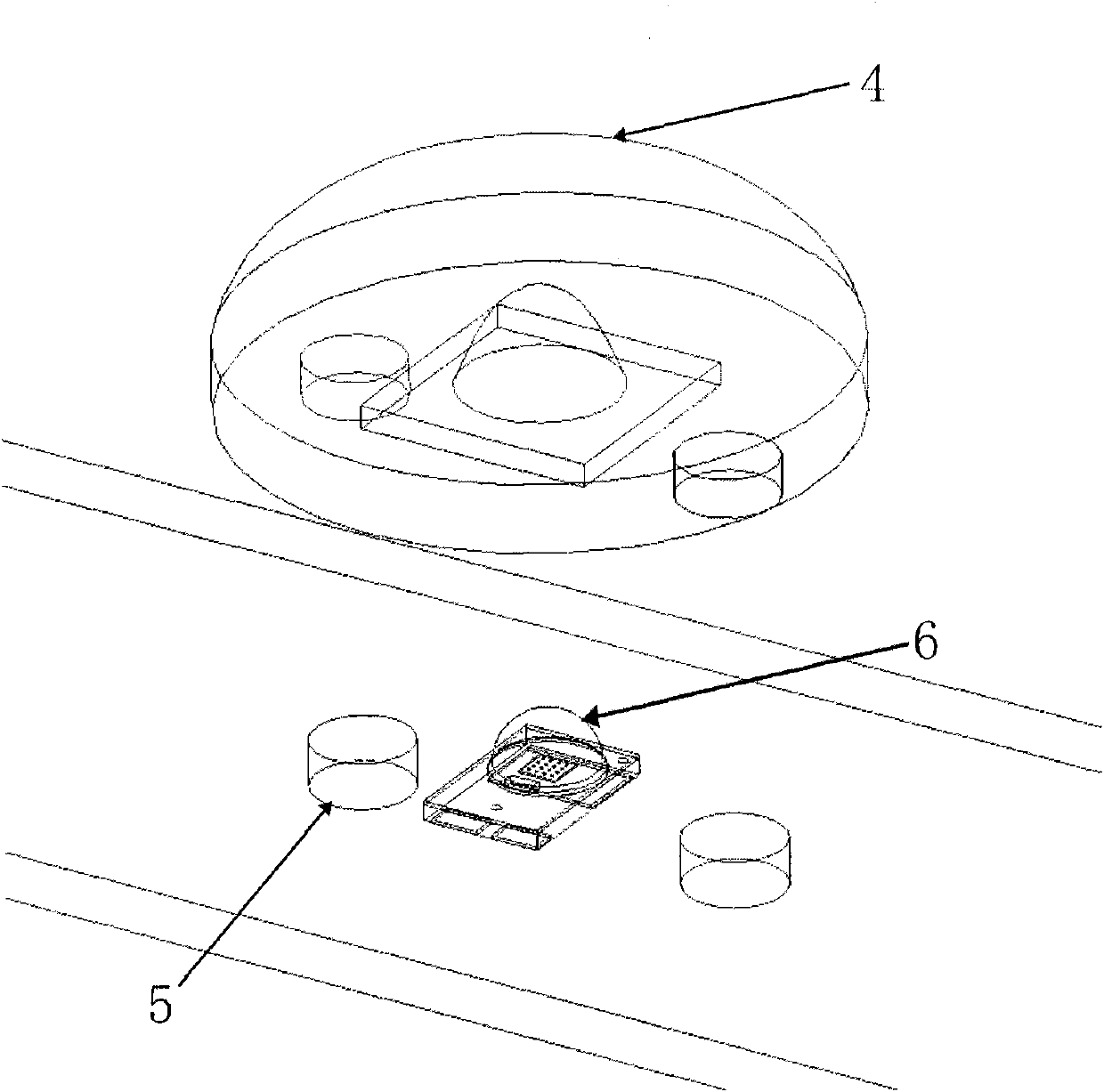
The invention relates to a dedicated wide-angle light-distribution lens for LEDs (light-emitting diode). The lens is a rotating body, which comprises an incident plane and an exit plane, wherein a concave pit with the inner curved surface thereof being a rotary surface formed by rotating a smooth curve is arranged on the incident plane of the LED lens, the top part of the curved surface is in smooth transition and the LED is arranged in the concave pit; the exit plane is particularly a rotary surface in smooth transition; and the center of the LED lens is particularly a concave plane gradually bulging in outward transition and bending downwards at the edge. The invention solves the problem of light spots in LED illumination and achieves the application of illumination-grade high-power LEDs as light sources in the illumination of even surfaces; and the invention ensures the stable LED single-lamp performance, reduces the number of the LED single-lamp and ensures the long service life and good reliability of the system.
Description
Technical field: The invention relates to a lens, in particular to a wide-angle light distribution lens dedicated to LEDs. Background technique: As a green and energy-saving light source, LED light sources are gradually replacing traditional light sources in the field of lighting. Compared with low-power LEDs, high-power LEDs have higher luminous efficiency, better color rendering index, and more stable temperature and light decay characteristics. It is the mainstream direction of LED light sources for lighting, and it is also the mainstream direction of research and development by international LED manufacturers. However, due to the high brightness of a single high-power LED, it is currently mainly used in key lighting areas such as spotlights and road lighting. Floodlighting lamps for commercial or home use are still dominated by small and medium-power LEDs below 1 watt, such as 3528 and 5050. There are two main types of LED surface light source lighting: 1) Side-lig...
Claims
Login to View More Application Information
Patent Timeline
 Patent Type & AuthorityApplications(China)
IPC IPC(8): F21V5/04F21V17/00F21V19/00F21Y101/02
Inventor黄瑞彬肖伟钟雄朱庆山
OwnerSHENZHEN JIUZHOU OPTOELECTRONICS TECH