
Light source device for slit lamp microscope

A slit lamp microscope and light source device technology, which is applied to fundus mirrors, electrical components, electrical solid devices, etc., can solve the problems of complex slit lamp mechanical structure, etc., and achieve the effects of easy design, installation and positioning, stable color, and small size

Inactive Publication Date: 2006-10-18
苏州六六视觉科技股份有限公司
View PDF0 Cites 3 Cited by
  • Summary
  • Abstract
  • Description
  • Claims
  • Application Information

AI Technical Summary

Problems solved by technology

In this way, the mechanical structure of the slit lamp becomes complicated, and limited by the types of color filters in the color filter group, it can only emit a limited number of colored lights.

Method used


Image

  • Light source device for slit lamp microscope
  • Light source device for slit lamp microscope
  • Light source device for slit lamp microscope

Examples


Embodiment

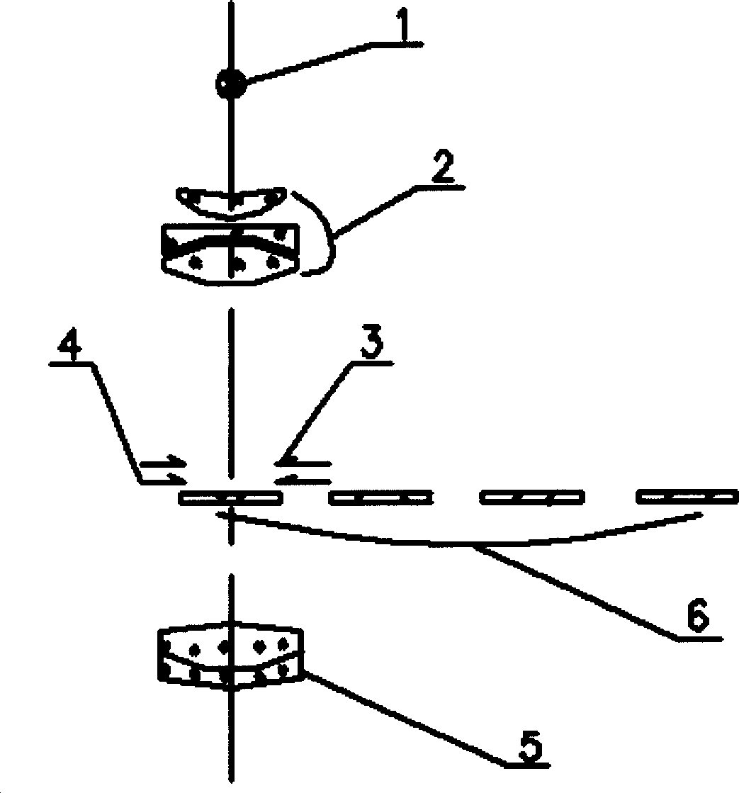
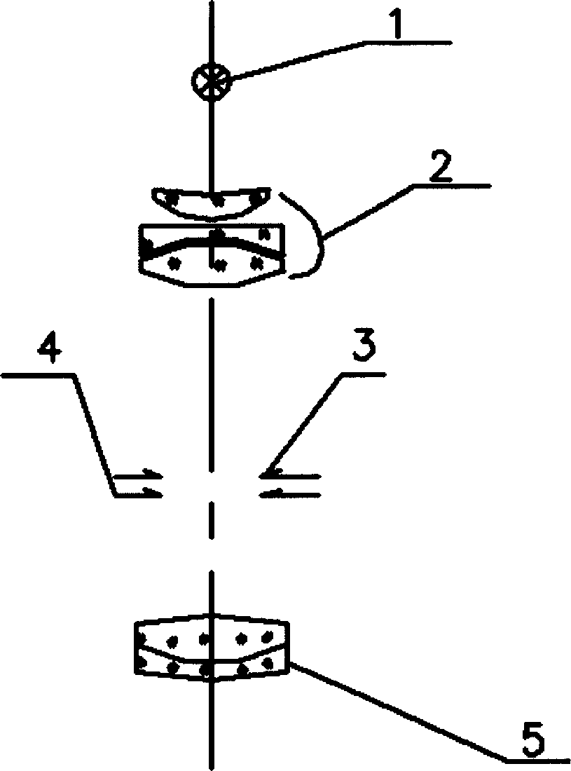
[0022] Example: such as image 3 , Figure 4 As shown, a light source device for a slit lamp microscope includes an illuminator 1, and a condenser lens group 2, a slit 3, a diaphragm 4, and a projection lens group 5 are sequentially arranged on the optical path of the illuminator 1; the illuminator 1 consists of A plurality of light emitting diodes 7 that emit light of different colors are combined, and at least there are light emitting diodes 7 that emit red light, blue light, and green light respectively.

[0023] Another embodiment of the present invention: as Figure 5 As shown, compared with the previous embodiment, in this embodiment, the illuminator 1 uses a multi-die light-emitting diode 8, and the multi-die light-emitting diode 8 encapsulates three kinds of light-emitting diodes that emit red light, blue light, and green light respectively. Die 9 of the diode.


PUM


Abstract

The present invention discloses one kind of light source device for slit lamp microscope. The light source device contains a lighter, and condensing lens set, slit, diaphragm and projecting lens set in the light path of the lighter. The lighter is one multiple die LED with red light emitting LED die, blue light emitting LED die and green light emitting LED die. The light source device has simple structure, convenient operation, rich light colors, high light homogeneity and high color stability, and can result in improved diagnosis quality.

Description

technical field [0001] The invention relates to a light source device, in particular to a light source device for a slit lamp microscope. Background technique [0002] A slit lamp is an optical instrument used to examine the eye. It includes an illuminator part, through some optical devices and slits, a slit image or a light spot is formed on the eye, and the user observes whether there are signs of disease in the human eye through a stereo microscope. [0003] The illuminator of the slit lamp generally used at present all is to adopt incandescent bulb or tungsten halogen bulb, and they all have certain deficiency. For example: ①Incandescent bulbs or tungsten-halogen bulbs have larger filaments, so the light intensity of the spot or crack image projected on the eye surface through the optical system is not so uniform, which will affect the user's observation; The strength of the brightness, the light passing through the color filter, the spectrum will change, and the wavel...

Claims


Application Information

Patent Timeline
Patent Type & Authority Applications(China)
IPC IPC(8): A61B3/135H01L25/075H01L25/13
Inventor 王萌建
Owner 苏州六六视觉科技股份有限公司
Learn More