Shielding gas flow controller for a welding apparatus

A technology of flow controller and shielding gas, which is applied in the direction of using electric device flow control, flow control, welding equipment, etc.

Active Publication Date: 2013-07-24
ALEXANDER BINZEL SCHWEISSTECHN GMBH & CO
View PDF5 Cites 0 Cited by
  • Summary
  • Abstract
  • Description
  • Claims
  • Application Information

AI Technical Summary

Problems solved by technology

Using the same regulation techniques will also solve the same problem of controlling gas flow in plasma cutting operations

Method used


Image

  • Shielding gas flow controller for a welding apparatus
  • Shielding gas flow controller for a welding apparatus
  • Shielding gas flow controller for a welding apparatus

Examples


Embodiment Construction

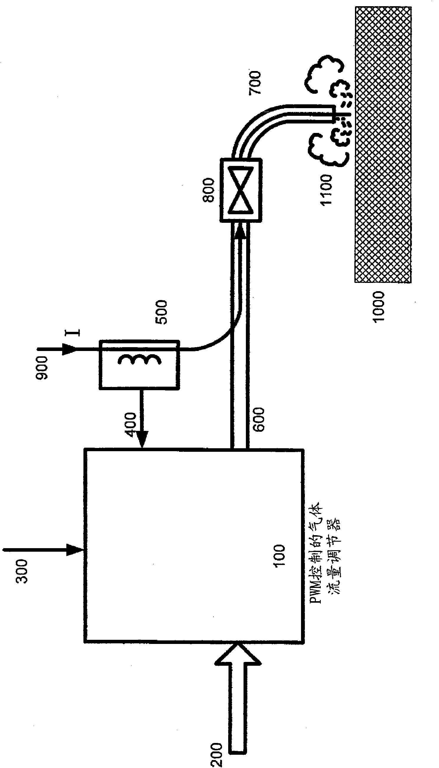
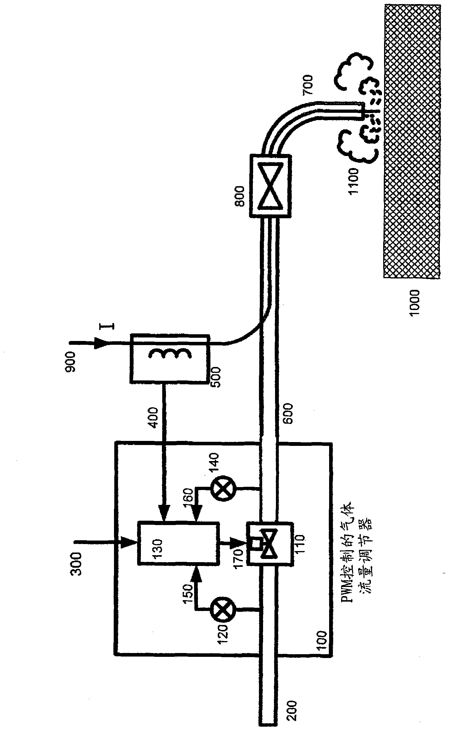
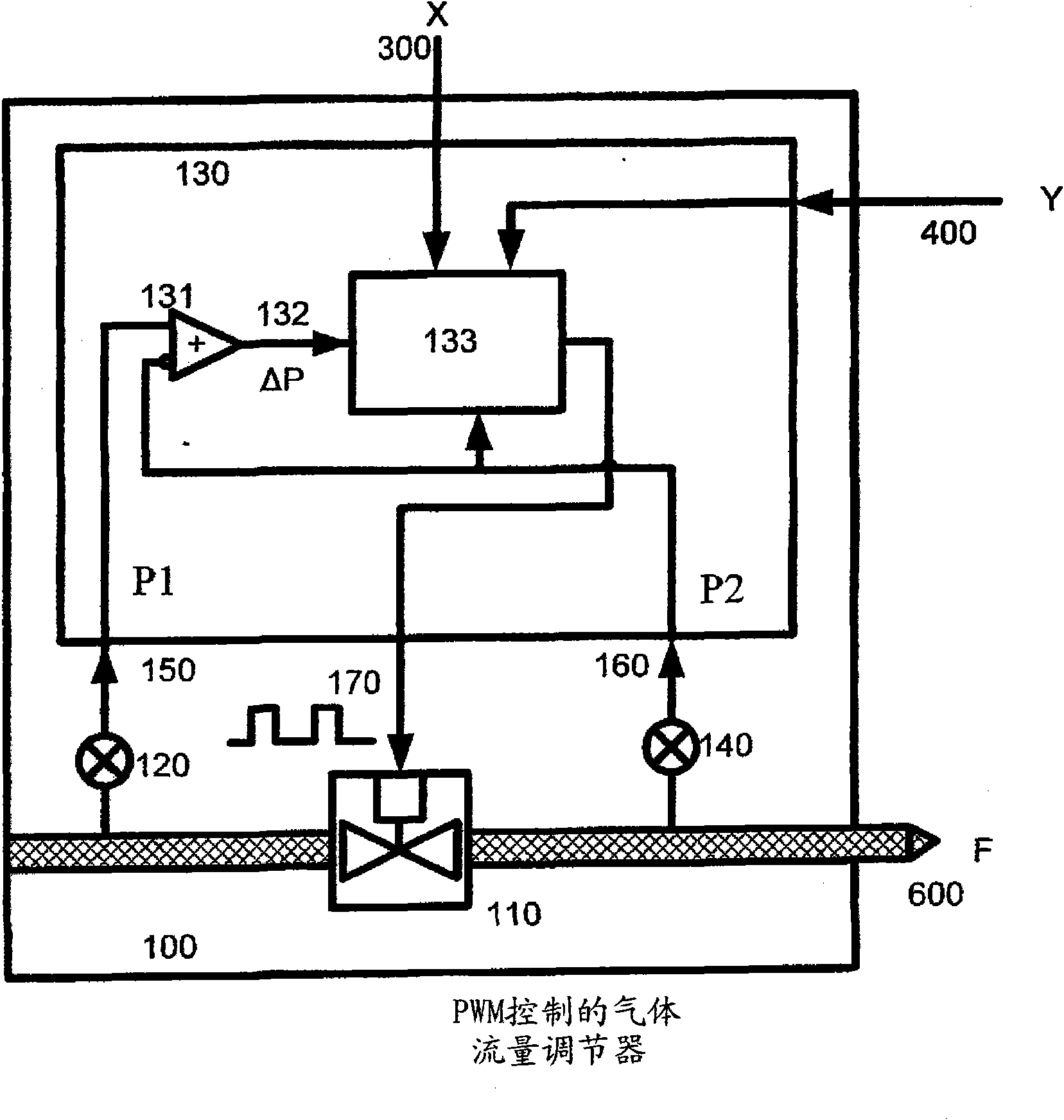
[0022] see figure 1 and figure 2 , the present invention provides an improvement in gas flow stability by automatically controlling the average time the valve remains open, thereby reducing the flow variation typically experienced in prior art welding gas supply installations. In a welding gas supply installation, the gas is supplied from a feed point 200 which will be arranged at a distance from the regulator 100 . In such prior art installations, it is common to locate the regulator 100 at a considerable distance from the gas final exit point 1100 . These distances will generally vary from one facility to another, and the dimensions of supply hoses, pipes, tubing, adapters and connectors will vary, with the result that gas flow levels will be affected, Such as Figure 8 As shown in the measurements performed in , and thus the flow needs to be adjusted in response to pressure changes in order to keep flow levels within acceptable tolerances.

[0023] The gas flow control...


PUM


Abstract

A shielding gas (SG) flow controller for an arc welder includes SG input / output with a controllable valve therebetween, and having a control input, and a controller having a first input receiving a welding signal representing arc current and a gas flow setting controller generating a flow setting output based on the welding signal, representing a desired SG flow. Input and output pressure sensors provide SG input and out pressure to second and third controller inputs, respectively. A flow setting output modifier modifies the flow setting output of the gas flow setting controller based on the SG input / output pressure, the welding signal, and a characteristic of the controllable valve into a control signal input to the control input of the controllable gas valve to maintain a substantially constant SG flow corresponding to the flow setting output substantially independent of actual SG input / output pressures.

Description

technical field [0001] The present invention relates to the field of providing filling gas or shielding gas (blanket gas), also known as shielding gas (shielding gas) or active gas, to welding points in electric welding equipment, and in particular to a method for use in various welding operations. A method and device for controlling the flows of shielding gas, shielding gas and active gas in stages. The field of the invention also relates to gas regulation for plasma cutting machines, wherein the flow of cutting gas (primary gas), shielding gas (secondary gas) or both is controlled by using the technical solutions provided by the present invention. Background technique [0002] For electric welding operations in which a shield of inert shielding gas is provided to the weld, the shielding gas is typically supplied from a centralized shielding gas supply facility, or from gas cylinders located near the welder unit of the welding apparatus. The shielding gas provided by the s...

Claims


Application Information

Patent Timeline
Patent Type & Authority Patents(China)
IPC IPC(8): B23K9/16B23K9/32G05D7/06
CPCB23K9/325G05D7/0635H05H1/341B23K9/173H05H2001/3494B23K9/0956G01M3/2815H05H1/3494
Inventor A·哈尔沃森M·法尔斯塔德
Owner ALEXANDER BINZEL SCHWEISSTECHN GMBH & CO
Why Eureka
Try Eureka