Dual-mass flywheel

A dual-mass flywheel, flywheel technology, applied in vibration suppression adjustment, spring/shock absorber, mechanical equipment, etc., can solve problems such as inapplicability of spring characteristic curve, and achieve the effect of compact structure

Inactive Publication Date: 2010-10-06
MAGNA POWERTRAIN AG & CO KG
View PDF0 Cites 9 Cited by
  • Summary
  • Abstract
  • Description
  • Claims
  • Application Information

AI Technical Summary

Problems solved by technology

The generally linear spring characteristic curve of the known dual-mass flywheels has also proven to be unsuitable for all applications

Method used


Image

  • Dual-mass flywheel
  • Dual-mass flywheel
  • Dual-mass flywheel

Examples


Embodiment Construction

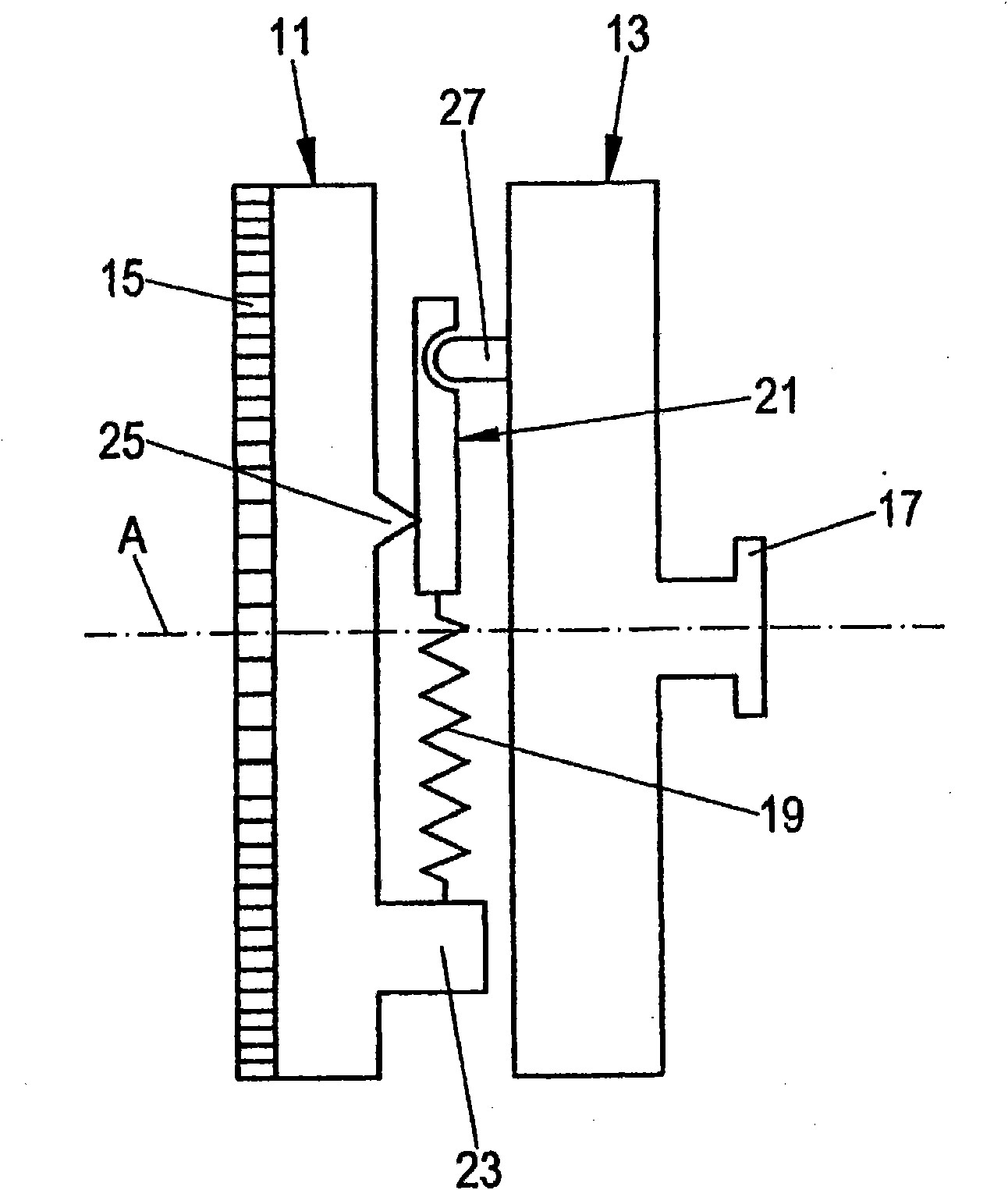
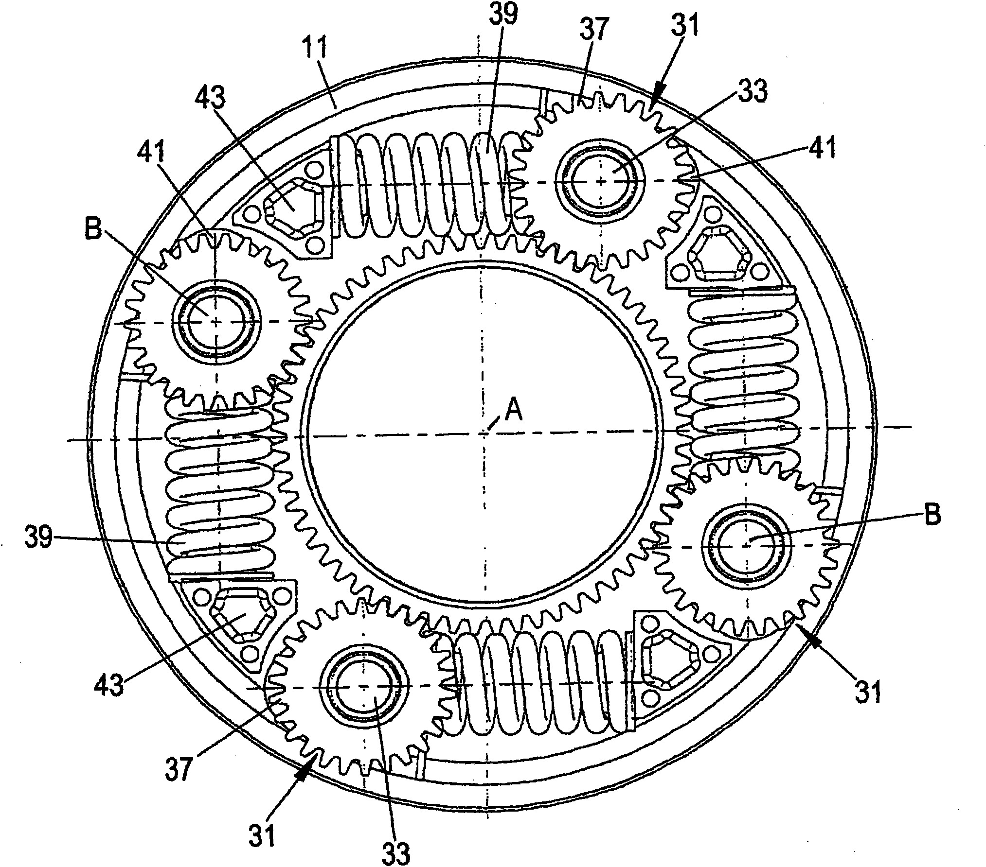
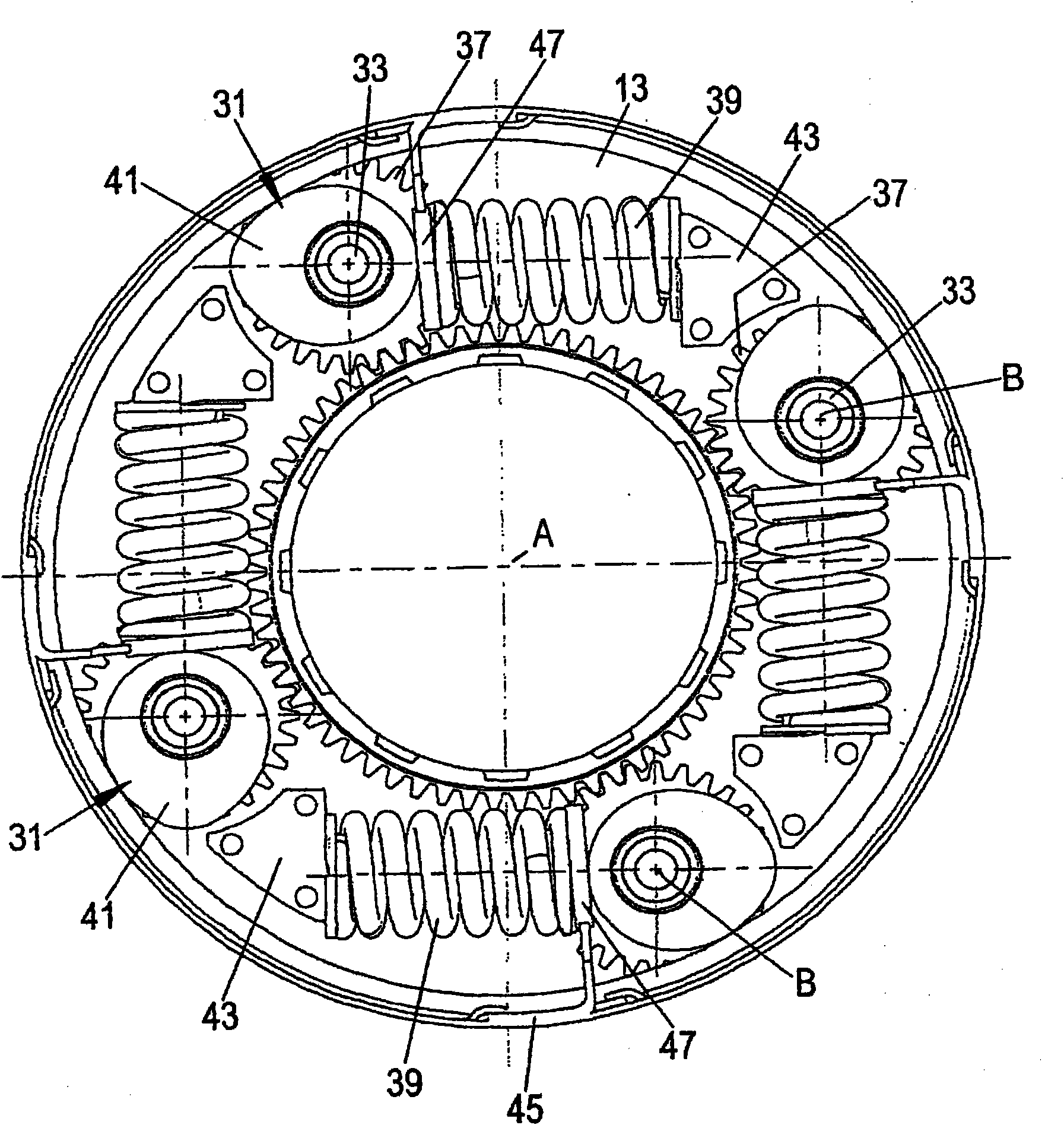
[0031] figure 1 A dual-mass flywheel is shown schematically, comprising a primary flywheel 11 and a secondary flywheel 13 , which are mounted rotatably about a common axis of rotation A. FIG. The primary flywheel 11 is connected, for example via a ring gear 15 , to the output of the motor vehicle engine in a rotationally efficient manner. Instead of the ring gear 15 , for example, fastening flanges or mating teeth can also be provided. The secondary flywheel 13 is connected, for example, via a fastening flange 17 to a clutch of a gearbox or to a torque converter of a vehicle transmission, wherein alternatively the connection can also be realized by means of a toothed arrangement or a one-piece construction.

[0032] A dual-mass flywheel is used in a known manner to absorb and damp torsional elastic vibrations. For this purpose, the two flywheels 11 and 13 are torsionally connected to each other via a spring mechanism 19, that is to say, the two flywheels 11 and 13 can rotate...


PUM


Abstract

The present invention relates to a dual-mass flywheel for a drive train of a motor vehicle, having one primary flywheel mass and one secondary flywheel mass (13), which are coupled to one another in a rotationally elastic manner via at least one spring device (19, 39, 53). At least one gear device (21, 31, 51, 51'') is disposed between the spring device and at least one of the two flywheel masses, said gear device causing a deflection movement of the spring device relative (19, 39, 53) to a rotational movement of the two flywheel masses in relation to one another, wherein a characteristic curve of the spring device may be modified by the gear device (21, 31, 51, 51'').

Description

technical field [0001] The invention relates to a dual-mass flywheel of a motor vehicle drive train, comprising a primary flywheel and a secondary flywheel, which are torsionally elastically coupled to each other by at least one spring mechanism. Background technique [0002] Such dual-mass flywheels are used in automobiles to temporarily store kinetic energy during engine idling and to absorb and damp torsional vibrations between the engine and drive train. In vehicles with a gearbox, for example, the primary flywheel is connected in a rotationally fixed manner to the engine crankshaft, and the secondary flywheel is connected in a rotationally fixed manner to the clutch of the gearbox. The torsional vibrations transmitted to the primary flywheel via the crankshaft are damped only to the secondary flywheel and thus to the gearbox and other drive trains due to the spring mechanism and possible additional damping devices. [0003] In the known dual-mass flywheels, the spring ...

Claims


Application Information

Patent Timeline
Patent Type & Authority Applications(China)
IPC IPC(8): F16F15/131F16F15/134
CPCF16F15/134F16F15/13157
Inventor 马丁·肖伯克里斯蒂安·贝纳茨基格尔德·施拉格雅罗斯拉夫·鲁托斯拉夫斯基
Owner MAGNA POWERTRAIN AG & CO KG
Why Eureka
Try Eureka