Electric vehicle braking system, control method and electric vehicle

A technology of electric vehicles and braking systems, which is applied in the direction of braking transmissions, brakes, vehicle components, etc., and can solve problems such as excessive braking and affecting the driver's judgment

Pending Publication Date: 2019-03-08
XIAMEN GOLDEN DRAGON BUS
View PDF0 Cites 3 Cited by
  • Summary
  • Abstract
  • Description
  • Claims
  • Application Information

AI Technical Summary

Problems solved by technology

At this time, it will affect the driver's judgment, mistakenly t

Method used


Image

  • Electric vehicle braking system, control method and electric vehicle
  • Electric vehicle braking system, control method and electric vehicle
  • Electric vehicle braking system, control method and electric vehicle

Examples


no. 1 example

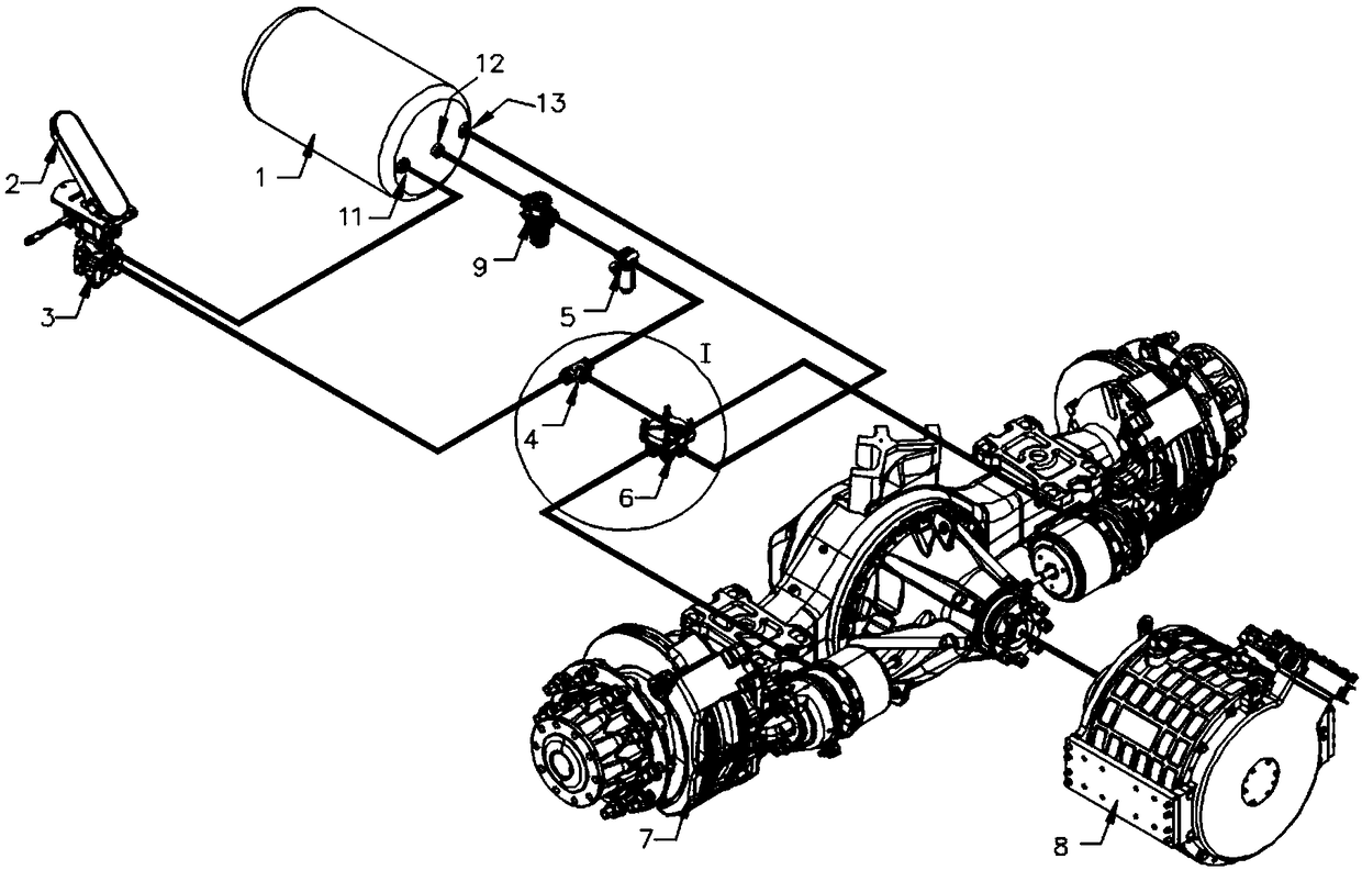
[0042] combine figure 1 , this embodiment provides an electric vehicle braking system, including: an air reservoir 1, a brake pedal 2, a master brake valve 3, a two-way check valve 4, a solenoid valve 5, a relay valve 6, a brake 7, Motor 8, battery (not shown) and vehicle controller (not shown).

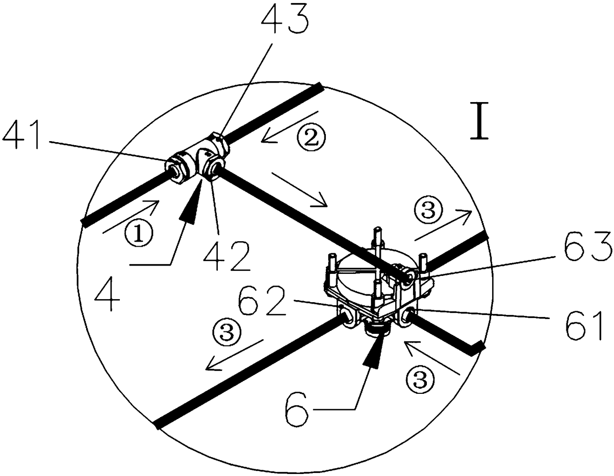
[0043] Please refer to figure 2, where the arrow direction is the ventilation direction, ① is the ventilation direction of the first air outlet 11, ② is the ventilation direction of the second air outlet 12, and ③ is the ventilation direction of the third air outlet 13. In this embodiment, the first air outlet 11 of the air storage tank 1 is connected to the first air inlet 41 of the two-way one-way valve 4 through the master brake valve 3, and the air outlet 42 of the two-way one-way valve 4 is connected to the relay valve 6, To form the first air pressure brake circuit. The second air outlet 12 of the air storage tank 1 is connected to the second air inlet 43 of the two-way che...

no. 2 example

[0052] refer to Figure 4 to Figure 5 , Figure 4 It is a schematic flowchart of a control method for an electric vehicle braking system according to the third embodiment of the present invention. Figure 5 It is a control flow diagram of the control method of the braking system of the electric vehicle according to the third embodiment of the present invention. The control method of the electric vehicle braking system can be executed by the vehicle controller, and specifically includes:

[0053] S10, acquiring the current pedal opening of the brake pedal 2 .

[0054] Wherein, the pedal opening of the brake pedal 2 can be measured by an angle sensor arranged on the brake pedal 2 , of course, it can also be measured by other methods, which are not specifically limited in the present invention.

[0055] S20, when the pedal opening is smaller than the preset opening threshold, acquire the current remaining power of the battery.

[0056] In this embodiment, the opening threshol...

no. 3 example

[0070] The third embodiment of the present invention provides an electric vehicle, including the braking system of the electric vehicle as described in the first embodiment.


PUM


Abstract

The invention provides an electric vehicle braking system, control method and electric vehicle, and relate to the technical field of electric vehicles; the electric vehicle braking system comprises anair storage cylinder, a brake pedal, a brake master valve, a two-way check valve, an electromagnetic valve, a relay valve, a brake, a battery, a motor and a whole vehicle controller; a first air outlet of the air storage cylinder is connected with a first air inlet of the two-way check valve through the brake master valve; an air outlet of the two-way check valve is connected with the relay valveto form a first pneumatic brake loop; a second air outlet of the air storage cylinder is connected with a second air inlet of the two-way check valve through the electromagnetic valve; the air outletof the two-way check valve is connected with the relay valve to form a second pneumatic brake loop; a third air outlet of the air storage cylinder is connected to the air inlet of the relay valve; the whole vehicle controller is electrically connected with the motor, the electromagnetic valve and the battery. By adding the second pneumatic brake loop on the pneumatic braking system, the protection of the battery when the battery is fully charged is achieved, and the braking effect of the braking system of the electric vehicle is not influenced.

Description

technical field [0001] The invention relates to the technical field of automobile braking, in particular to an electric vehicle braking system, a control method and the electric vehicle. Background technique [0002] With the consumption of energy, the deterioration of the environment and the advancement of technology, the intelligentization and electrification of automobiles is the development trend of the automobile industry. Automobile intelligence makes automobile driving safer and more comfortable. Electric vehicles have the function of braking energy recovery, which can save energy. [0003] At present, the pure electric new energy buses in the industry use the motor braking system to realize energy recovery and vehicle deceleration, and combine the air pressure braking system to realize vehicle deceleration, parking and other functions. When the driver depresses the brake pedal, the motor braking system acts first, and when the brake pedal opening is greater than th...

Claims


Application Information

Patent Timeline
IPC IPC(8): B60T13/24B60T13/58B60T13/74B60L7/10
CPCB60T13/24B60L7/10B60T13/58B60T13/74
Inventor 石添华林剑健陈斌强林必生周朝锋尚小辉谢延兴
Owner XIAMEN GOLDEN DRAGON BUS
Why Eureka
Try Eureka