
An improvement of a tractor planetary end drive

A technology of tractors and planets, applied in the direction of transmission, transmission parts, gear transmission, etc., can solve problems such as uneven load, and achieve the effect of prolonging the service life

Active Publication Date: 2017-02-01
ZHEJIANG HAITIAN MACHINERY
View PDF3 Cites 0 Cited by
  • Summary
  • Abstract
  • Description
  • Claims
  • Application Information

AI Technical Summary

Problems solved by technology

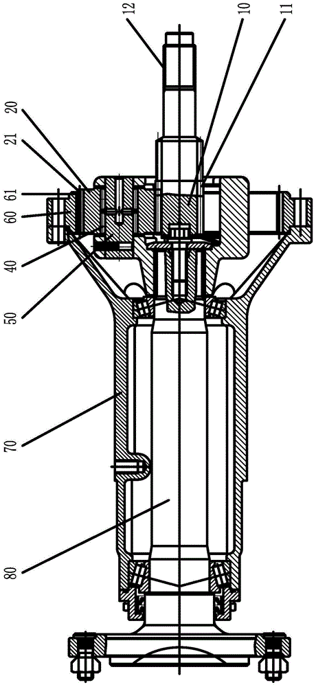
[0002] see figure 1 : At present, the planetary terminal drive of the tractor includes an output shaft 80 and a drive shaft 10 (or sun gear half shaft) arranged on a coaxial line. The output shaft 80 is covered with a shaft sleeve 70, and the drive shaft 10 is equipped with a sun gear 11. Three planetary gears 20 evenly distributed in the circumferential direction are installed on the planetary gear shaft 50 installed on the output shaft 80. The planetary gears 20 are meshed with the sun gear 11 for transmission. Teeth 61 are meshed with the gear teeth 21 of the planetary gear 20 for transmission. A bearing 40 is arranged between the planetary gear shaft 50 and the planetary gear 20. The spline 12 arranged on the drive shaft 10 is connected to the differential half shaft in the tractor gearbox. The spline connection of the gears, due to the manufacturing error of the ring gear with internal teeth, the planetary gear, and the inner planet carrier on which the planetary gear is installed, when the three planetary gears are meshed with the ring gear and the sun gear respectively, there is no difference in the tooth length direction. Even load, leading to early failure of the planetary gear

Method used


Image

  • An improvement of a tractor planetary end drive
  • An improvement of a tractor planetary end drive
  • An improvement of a tractor planetary end drive

Examples


Embodiment Construction

[0018] Below in conjunction with accompanying drawing, the present invention will be further described with specific embodiment, see figure 2 — Figure 4 :

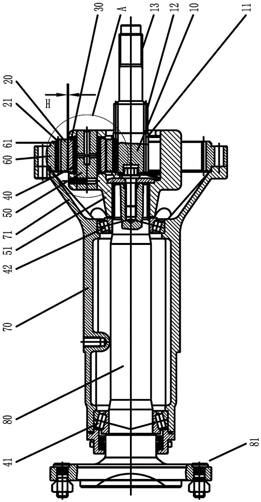
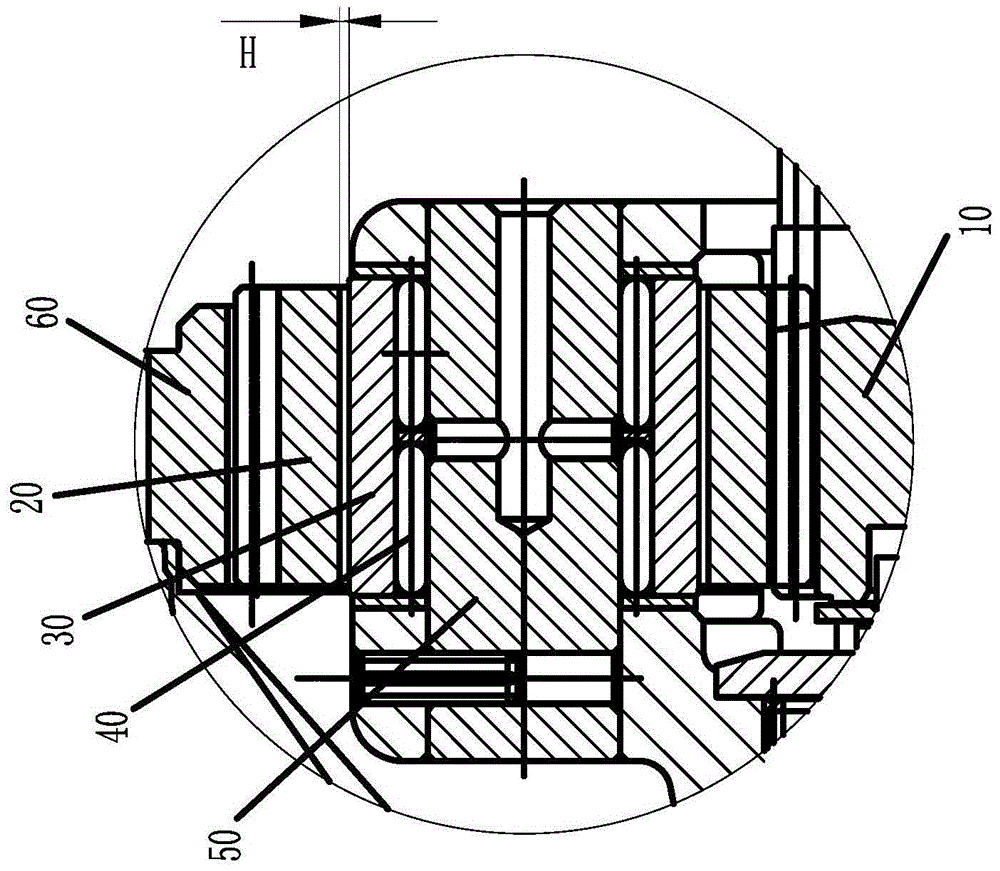
[0019] An improvement of a tractor planetary end drive, including an output shaft 80 and a drive shaft 10 arranged on coaxial lines, a shaft sleeve 70 is set on the output shaft 80, a sun gear 11 is set at one end of the drive shaft 10, and a The planetary gear 20 which meshes with the sun gear 11 is installed on the planetary shaft 50, and the ring gear 60 with internal teeth 61 provided on the bushing 70 is engaged with the external teeth 21 of the planetary gear 20 for transmission. A bearing 40 and an intermediate ring 30 are sequentially fitted between the planetary wheel shaft 50 and the planetary wheel 20 from inside to outside, and a radial floating gap H is provided between the planetary wheel 20 and the intermediate ring 30 .

[0020] The above planetary shaft 50 and the bearings 40 , the intermediate ring 30...


PUM


Abstract

The invention belongs to the technical field of final drive of tractors, and relates to an improvement in planet final drive of a tractor. The improvement comprises an output shaft and a driving shaft, wherein the output shaft and the driving shaft are coaxially arranged. The output shaft is sleeved with a shaft sleeve, a sun wheel is arranged at one end of the driving shaft, planet wheels meshed with the sun wheel for drive are installed on planet wheel axles installed on the output shaft, a gear ring arranged on the shaft sleeve and provided with internal teeth is meshed with the planet wheels for drive, a bearing and an intermediate ring are sequentially arranged between each planet wheel axle and the corresponding planet wheel in a sleeved mode from inside to outside, and radial floating intervals are formed between the planet wheels and the corresponding intermediate rings. The improvement has the advantages that the intermediate rings are arranged, the radial floating intervals are formed between the planet wheels and the corresponding intermediate rings to form buffer oil films, the planet wheels can be connected in a suspension mode, uniform loads of the planet wheels in the tooth length direction in the working process are guaranteed, and the service life of the planet wheels is prolonged.

Description

technical field [0001] The invention belongs to the technical field of tractor terminal transmission, in particular to an improvement of a tractor planetary terminal transmission. Background technique [0002] see figure 1 : At present, the planetary terminal drive of the tractor includes an output shaft 80 and a drive shaft 10 (or sun gear half shaft) arranged on a coaxial line. The output shaft 80 is covered with a shaft sleeve 70, and the drive shaft 10 is equipped with a sun gear 11. Three planetary gears 20 evenly distributed in the circumferential direction are installed on the planetary gear shaft 50 installed on the output shaft 80. The planetary gears 20 are meshed with the sun gear 11 for transmission. Teeth 61 are meshed with the gear teeth 21 of the planetary gear 20 for transmission. A bearing 40 is arranged between the planetary gear shaft 50 and the planetary gear 20. The spline 12 arranged on the drive shaft 10 is connected to the differential half shaft in ...

Claims


Application Information

Patent Timeline
Patent Type & Authority Patents(China)
IPC IPC(8): F16H1/32F16H57/08F16H57/023
CPCF16H1/2836F16H1/32F16H57/023F16H57/08F16H2001/327
Inventor 陈正文
Owner ZHEJIANG HAITIAN MACHINERY
Learn More