Eureka AIR delivers breakthrough ideas for toughest innovation challenges, trusted by R&D personnel around the world.

Infrared lamp irradiator

A technology of illuminating device and infrared lamp, applied in the direction of lighting device, fixed lighting device, parts of lighting device, etc., can solve the problem of excessive reflection of the object to be photographed, the inability to clearly identify the contour features of the object to be photographed, and the inability to distinguish the object from the picture. Identify the facial features of the subject and other issues, achieve uniform distribution of infrared light, and achieve the effect of no strong reflection

Inactive Publication Date: 2010-10-13
深圳市枫景树科技有限公司
View PDF5 Cites 14 Cited by
  • Summary
  • Abstract
  • Description
  • Claims
  • Application Information

AI Technical Summary

Problems solved by technology

[0003] During the use of these infrared lamp irradiation devices 12, the phenomenon of excessive reflection of the infrared light by the photographed object often occurs, so that the outline characteristics of the photographed object cannot be clearly recognized from the picture, for example, when the infrared lamp irradiation device 12 irradiates people When the face and eyes of the human body are exposed, the image of the person captured by the camera 11 at this time presents a white light except for the hair of the person, and the human eye is "glowing" due to the direct infrared rays, making it impossible to recognize it from the image. Subject's facial features
Above-mentioned present situation is because the irradiation mode of existing infrared lamp irradiation device 12 causes, as figure 1 As shown, the existing infrared lamp irradiation device 12 is fixed on the side of the camera 11, so when the camera 11 takes pictures of the scene, a "flashlight" irradiation phenomenon will occur. Dim, the resulting illumination contrast causes the subject to be overly reflective
In addition, there are currently used figure 2 The shown independent infrared lamp irradiation device is installed around the camera and turned on at night or when the ambient illumination is not enough, but the irradiation mode of the infrared lamp irradiation device is different from that of figure 1 The lighting method shown is the same, so there is also the problem of excessive reflection of the subject
In summary, due to the unreasonable irradiation mode of the existing infrared lamp irradiation device itself, the above-mentioned excessive reflection phenomenon is inevitable

Method used


Image

  • Infrared lamp irradiator
  • Infrared lamp irradiator
  • Infrared lamp irradiator

Examples


Embodiment Construction

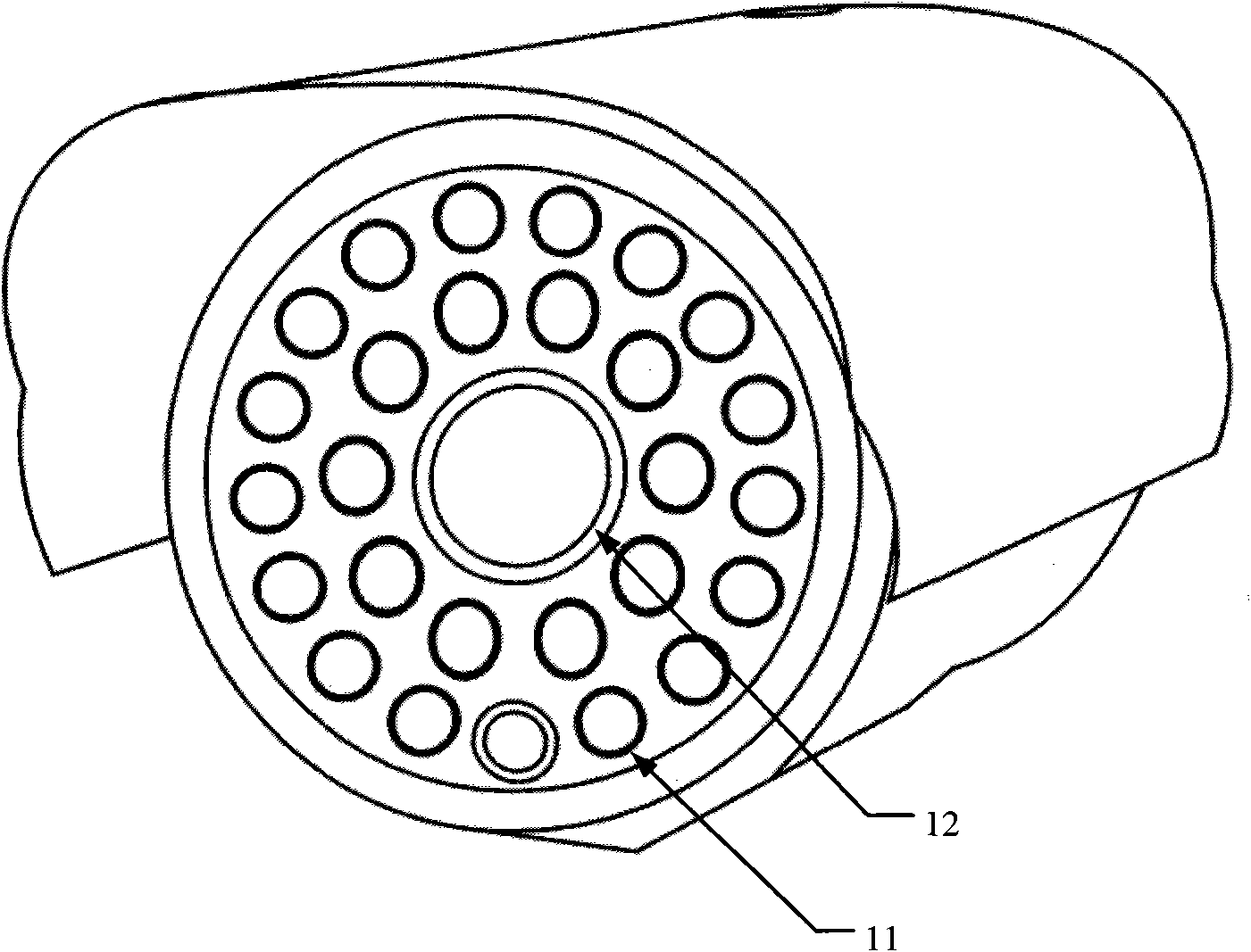
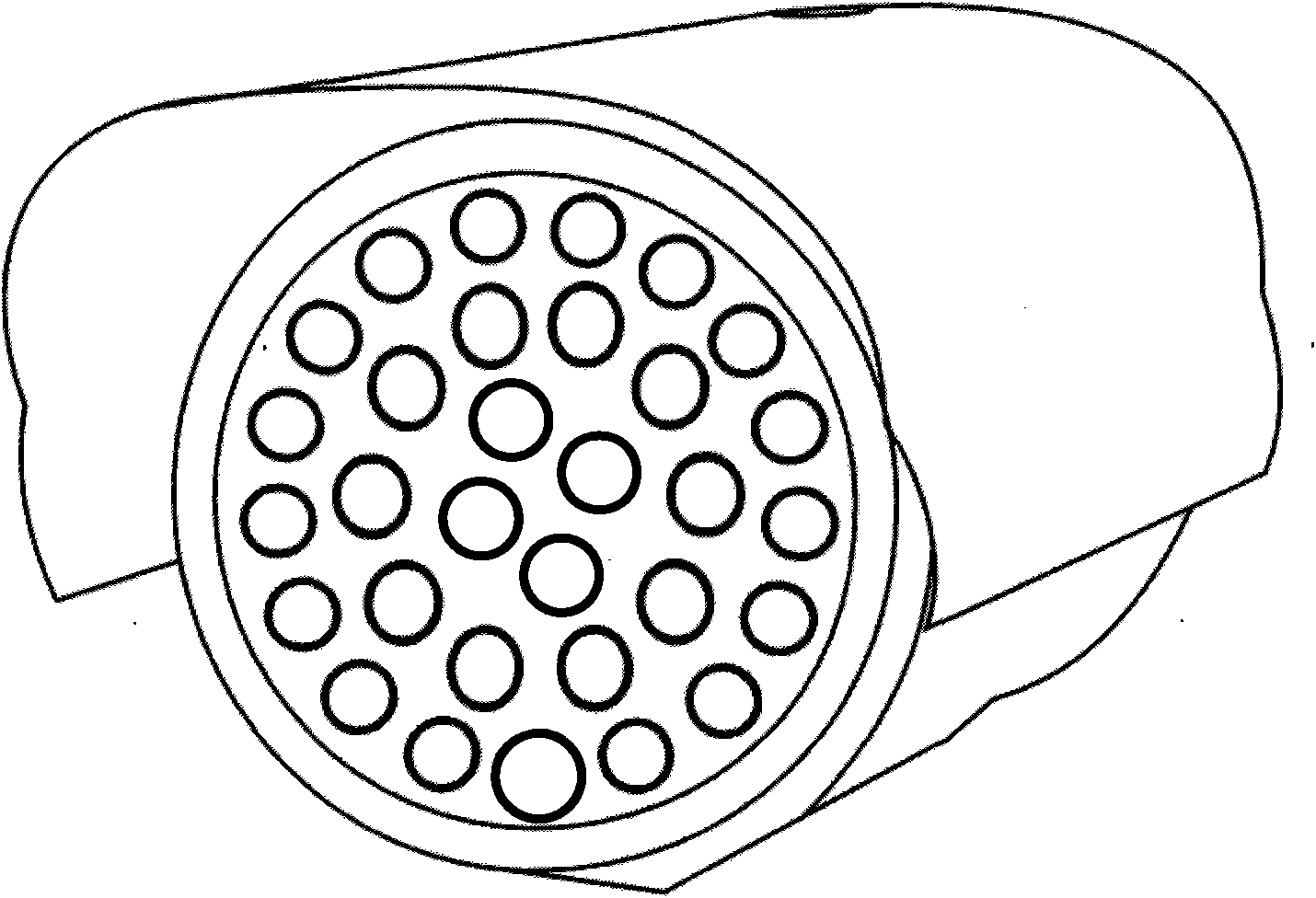
[0040] The invention proposes an infrared light irradiation device, which can make the infrared light distribution in the monitoring area uniform, realize no strong reflection of the object to be photographed, and achieve the effect that the camera can capture clear scenes when the visible light in the environment is insufficient or completely absent.

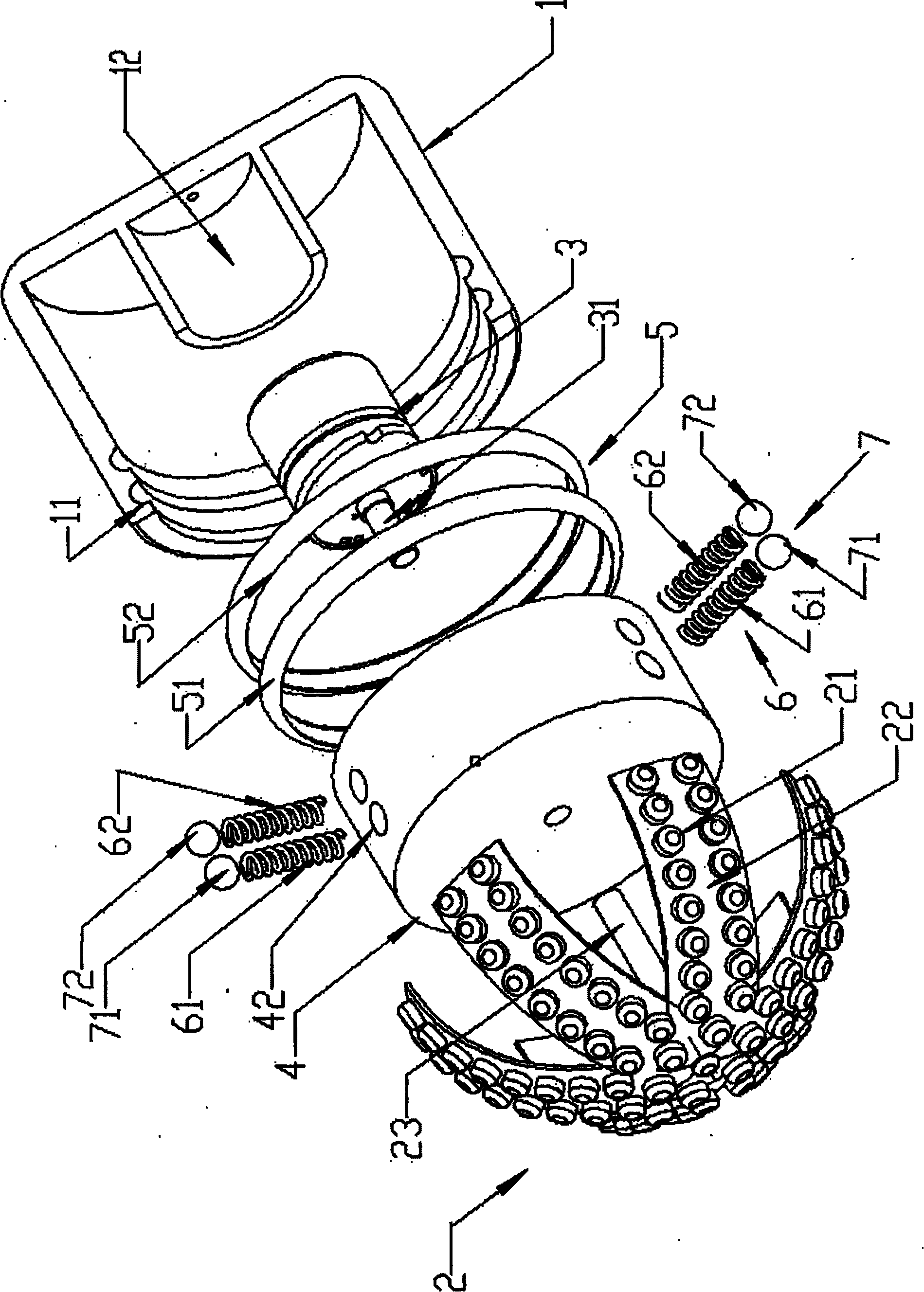
[0041] image 3 It is an exploded schematic diagram of the structure of the first embodiment of the infrared lamp irradiation device in the embodiment of the present invention, Figure 4 It is a schematic diagram of the structural combination of the first embodiment of the infrared lamp irradiation device in the embodiment of the present invention, combined with image 3 and Figure 4 In the embodiment of the present invention, the infrared lamp irradiation device includes a housing 1 and a lamp body 2 composed of infrared light-emitting diodes 21, and also includes a motor 3, a positioning and rotating conductive plate 4 for ...


PUM


Abstract

The invention provides an infrared lamp irradiator, which comprises a shell, a lamp body, a motor, a positioned rotary conductive disk and a conductive slide ring, wherein the lamp body comprises infrared light-emitted diodes, the positioned rotary conductive disk is used for supplying power to the lamp body, the conductive slide ring is used for supplying power to the positioned rotary conductive disk, and is arranged on the inner wall of the shell, the lamp body is arranged on the positioned rotary conductive disk and electrically connected with the positioned rotary conductive disk, the surface formed by the infrared light-emitted diodes on the lamp body makes an included angle less than 90 degrees with the top surface of the positioned rotary conductive disk, the center of the positioned rotary conductive disk is connected with the output shaft of the motor, and moreover, the positioned rotary conductive disk can be driven by the motor to rotate; and the positioned rotary conductive disk is electrically connected with the conductive slide ring, and can slide along the conductive slide ring. The implementation of the embodiment of the invention can ensure that the infrared light in a monitored area can be uniformly distributed and that a photographed object does not have strong reflected light, and thereby a camera can take a clear picture of a scenery under the condition of insufficient environmental visible light or no visible light.

Description

technical field [0001] The invention relates to the monitoring field, in particular to an infrared lamp irradiation device. Background technique [0002] Such as figure 1 As shown, the current monitoring equipment is equipped with a charge-coupled device (Charge-coupled Device, CCD) camera 11 and an infrared light irradiation device 12, and the infrared light irradiation device 12 will be turned on at night or when the ambient illumination is not enough, as a supplementary light source to assist the camera 11 Shoot the scenery so that the camera can still monitor normally in the dark. [0003] During the use of these infrared lamp irradiating devices 12, the phenomenon of excessive reflection of the infrared light by the photographed object often occurs, so that the outline characteristics of the photographed object cannot be clearly recognized from the picture, for example, when the infrared lamp illuminating device 12 illuminates a person When the face and eyes of the hu...

Claims


Application Information

Patent Timeline
Patent Type & Authority Applications(China)
IPC IPC(8): F21S8/00F21V14/02F21V19/00F21V23/00G03B15/05F21Y101/02
Inventor 封鸿涛林方剑郝新竹彭力
Owner 深圳市枫景树科技有限公司
Why Eureka
Eureka Blog
Learn More