Frequency converter drive protecting circuit
A technology for driving and protecting circuits and frequency converters, applied to electrical components, output power conversion devices, etc., can solve the problems of expensive frequency converter protection and insufficient functions, and achieve the effect of perfect protection function and low cost
- Summary
- Abstract
- Description
- Claims
- Application Information
AI Technical Summary
Problems solved by technology
Method used
Image
Examples
Embodiment Construction
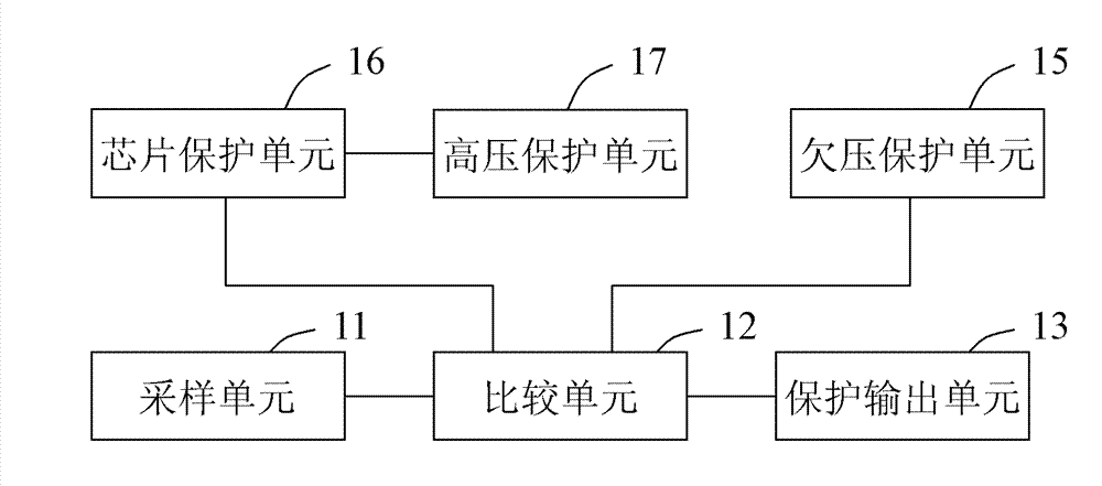
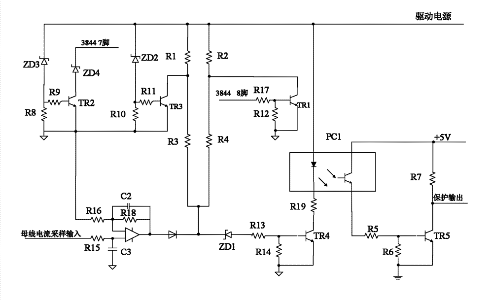
[0028] Such as figure 1 Shown is a logic block diagram of an embodiment of the inverter drive protection circuit of the present invention. In this embodiment, the circuit includes a sampling unit 11, a comparison unit 12, and a protection output unit 13, wherein the input of the sampling unit 11 is connected to the DC bus of the frequency converter, and the input of the comparison unit 12 is connected to the output of the sampling unit 11 The input terminal of the protection output unit 13 is connected to the output terminal of the comparison unit 12 . The above circuit outputs a protection signal through the protection output unit 13 when the current in the DC bus is too large (for example, a short circuit occurs).
[0029] The sampling unit 11 converts the current value of the inverter DC bus into a voltage value and outputs it to the input terminal of the comparison unit 12. If the comparison unit 12 judges that the input voltage value is greater than the first threshold v...
PUM
 Abstract
Description
Claims
Application Information
 - R&D
- Intellectual Property
- Life Sciences
- Materials
- Tech Scout
- Unparalleled Data Quality
- Higher Quality Content
- 60% Fewer Hallucinations
Browse by: Latest US Patents, China's latest patents, Technical Efficacy Thesaurus, Application Domain, Technology Topic, Popular Technical Reports.
© 2025 PatSnap. All rights reserved.Legal|Privacy policy|Modern Slavery Act Transparency Statement|Sitemap|About US| Contact US: help@patsnap.com


