Hinge and door device

一种门装置、铰链的技术,应用在铰链和门装置领域,能够解决费工夫等问题,达到紧凑收纳、防止追加部件、规模小型化的效果

Inactive Publication Date: 2010-10-13
CATEPILLAR SARL
View PDF1 Cites 1 Cited by
  • Summary
  • Abstract
  • Description
  • Claims
  • Application Information

AI Technical Summary

Problems solved by technology

[0007] In addition, with regard to the existing holding mechanism 19, when the side door 17 is opened, it should be as follows: Figure 34 As shown, the strut 19s is hooked between the holes of the brackets 19a and 19d in a straddling manner. However, since it is a position alignment operation accompanying the loading and unloading of the strut 19s, it takes a lot of work, and there are still some problems on the construction site. may omit the assignment

Method used


Image

  • Hinge and door device
  • Hinge and door device
  • Hinge and door device

Examples


Embodiment Construction

[0067] Below, refer to Figure 1 to Figure 11 The first embodiment shown, Figure 12 to Figure 16 The second embodiment shown, Figure 17 The third embodiment shown, Figure 18 to Figure 28 The fourth embodiment shown, Figure 29 The fifth embodiment shown and Figure 30 The sixth embodiment shown will describe the present invention in detail.

[0068] first of all, yes Figure 1 to Figure 11 The first embodiment shown will be described.

[0069] Figure 7 Shown is a hydraulic excavator 10 as an operating machine, and an upper revolving body 12 is rotatably provided on a lower traveling body 11 , and a driver's cab 13 , a working device 14 , and a power unit 15 such as an engine are attached to the upper revolving body 12 . The power unit 15 is covered by an upper cover 16, a side door 17, and the like.

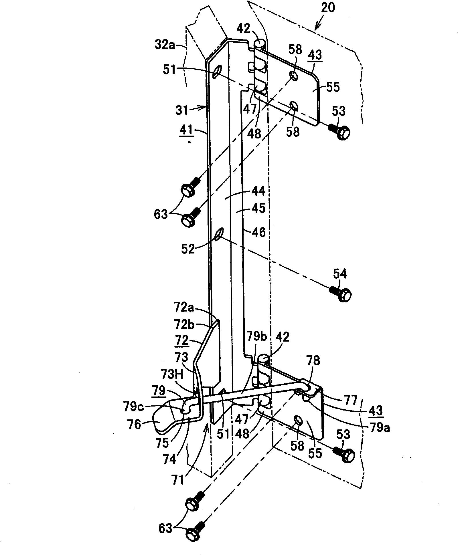
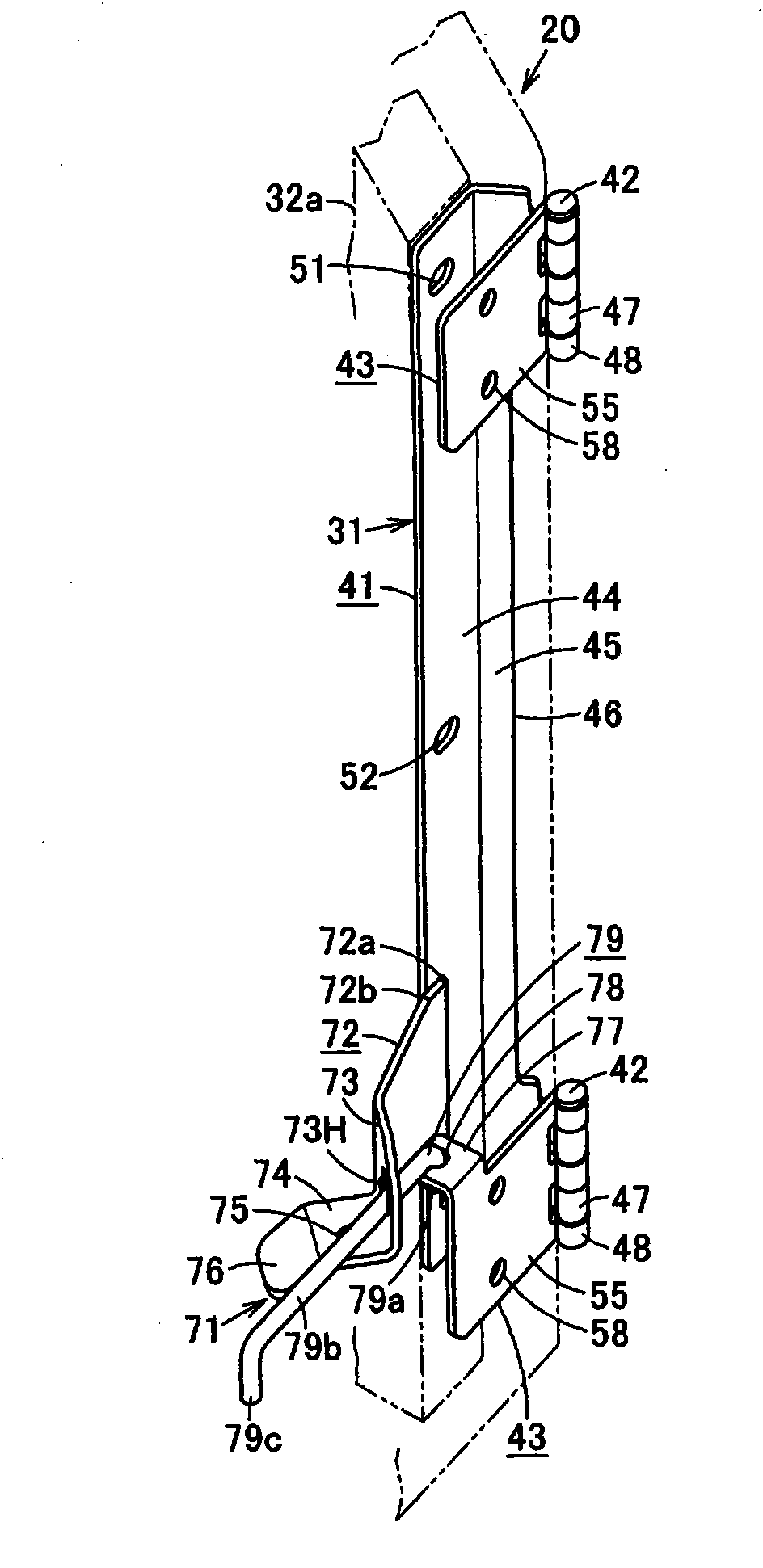
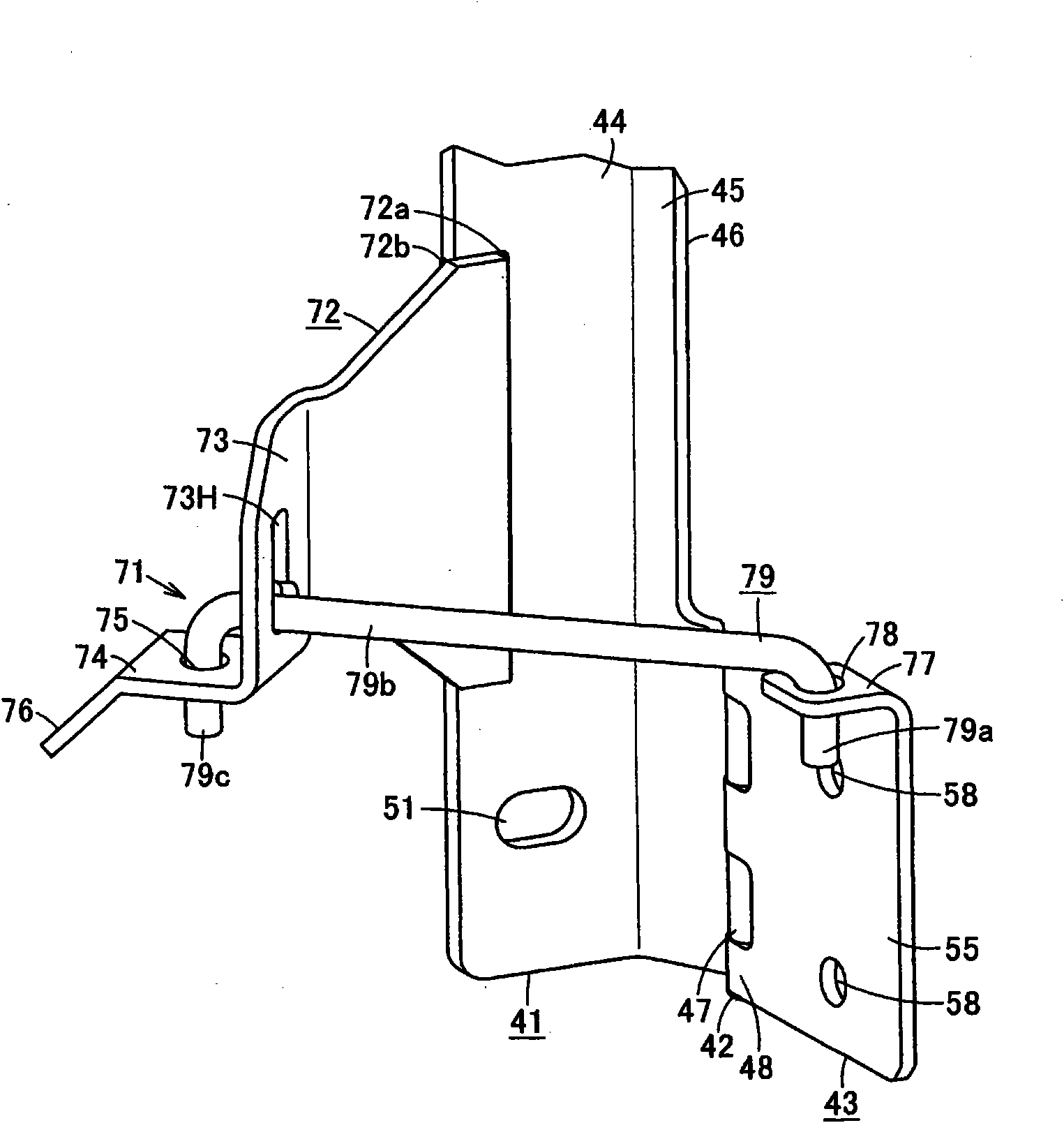
[0070] Such as Figure 8As shown, one side of the door panel main body 20 of the side door 17 is installed on the frame 32 on the side of the machine body through a ...


PUM


Abstract

The invention provides a hinge for reliably holding a door open state without requiring additional mounting of a bracket on a frame and a door member. One hinge plate 41 rotatably supports thereon the other hinge plate 43 by a shaft member 42 in an openable and closable manner. A bracket section 77 is formed integrally with the upper edge of an end of the other hinge plate 43, which is located on the side opposite the side on which the shaft member 42 is mounted, and a vertical shaft section 79a of a hold-stay rod 79 is loosely fitted in a shaft hole 78 in the bracket section 77 so as to be pivotable and vertically slidable. A horizontal shaft section 79b of the hold-stay rod 79 is slidably inserted in a guide hole 73H in a guide plate 72 welded to the hinge plate 41, and an locking section 79c is formed by bending at the front end of the hold-stay rod 79. When the other hinge plate 43 is opened, the engaging section 79c is moved from a guide section 76 to a receiving plate section 74 and inserted into an engaging hole 75. The engaging section 79c is removed from the engaging hole 75 by pushing the engaging section up by a finger.

Description

technical field [0001] The present invention relates to a hinge for attaching a door panel main body to a frame, and a door device that can be freely opened and closed by the hinge. Background technique [0002] Figure 31 Shown is a hydraulic excavator 10 as an operating machine, and an upper revolving body 12 is rotatably provided on a lower traveling body 11 , and a driver's cab 13 , a working device 14 , and a power unit 15 such as an engine are attached to the upper revolving body 12 . The power unit 15 is covered by an upper cover 16, a side door 17, and the like. Side door 17 is installed to be able to open and close freely by hinge 18, through Figure 32 to Figure 34 A holding mechanism 19 is shown to hold the side door 17 open. [0003] about the Figure 32 to Figure 34 Shown existing retaining mechanism 19, when closing side door 17, as Figure 33 As shown, the strut (round rod) 19s bent into a U-shape is accommodated across the holes between the brackets 19a a...

Claims


Application Information

Patent Timeline
Patent Type & Authority Applications(China)
IPC IPC(8): E05C17/22B62D25/12E02F9/00E05C17/20E05D11/06
CPCE02F9/00E05C17/14E05C17/22E05Y2900/531E05Y2900/518E02F9/0891E05D11/06
Inventor 宇户亮二横川庆太郎后藤隆弘竹内重美
Owner CATEPILLAR SARL
Why Eureka
Try Eureka