Engine-mounting bracket

A technology of engine mounts and mount cushions, which is applied to power plants, jet propulsion devices, internal combustion propulsion devices, etc., can solve the problems of increased number of engine parts, poor engine NVH performance, high management and manufacturing costs, and achieve structural Effects of compactness, reduction in the number of mounting bolts, and reduction in management and manufacturing costs

Inactive Publication Date: 2013-04-03
CHONGQING CHANGAN AUTOMOBILE CO LTD
View PDF5 Cites 0 Cited by
  • Summary
  • Abstract
  • Description
  • Claims
  • Application Information

AI Technical Summary

Problems solved by technology

In the past, the engine mount bracket on the transmission side and the clutch cable mounting bracket were independent and were arranged separately on the transmission. This arrangement reduced the effective layout space of the engine mount bracket and increased the risk of resonance. The NVH of the engine Poor performance; on the other hand, the number of parts of the engine also increases, and the management and manufacturing costs are high

Method used


Image

  • Engine-mounting bracket
  • Engine-mounting bracket
  • Engine-mounting bracket

Examples


Embodiment Construction

[0014] Further illustrate structure of the present invention below in conjunction with accompanying drawing:

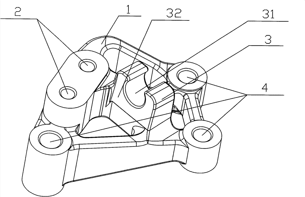
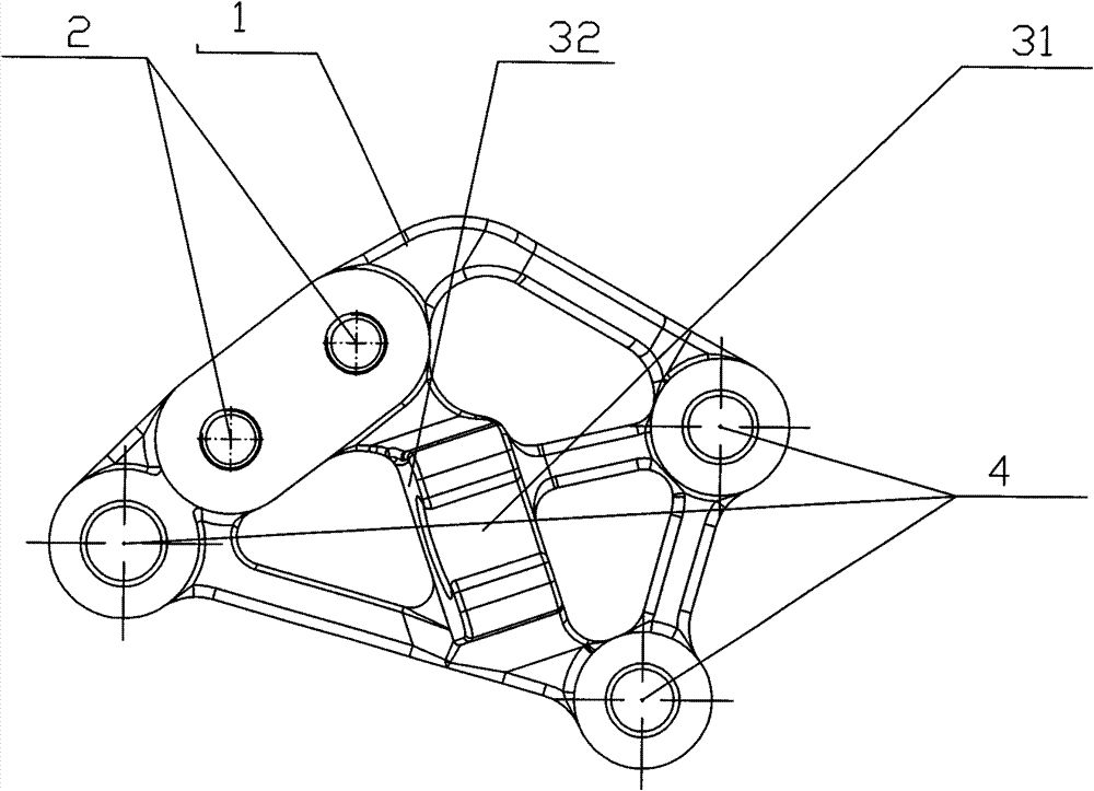
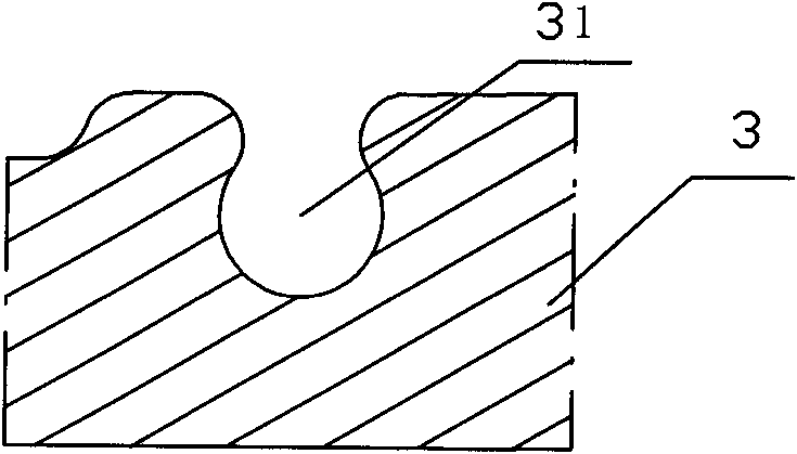
[0015] Such as Figure 1 to Figure 2 As shown, the main body of the engine mount bracket is an integrally formed quadrilateral bracket body 1, and three corners of the bracket body 1 are respectively arranged with transmission mounting holes 4. One side of the bracket body 1 is integrally formed with a suspending cushion mounting boss 2, and the boss has mounting holes. There is a reinforcing beam in the middle of the bracket body 1, on which a clutch cable guide 3 is integrally formed. see image 3 , the clutch cable guide 3 is a boss structure with a horizontal slot, the slot is the guide track 31 of the clutch cable, and the side wall of the boss is the guide limit plane 32 of the flange surface of the clutch cable head.

[0016] see Figure 4 , the engine suspension bracket assembly 6 connects the powertrain and the vehicle body through the suspension cushion ...


PUM


Abstract

The invention provides an engine-mounting bracket, which is provided with a bracket body, transmission-mounting holes for the mounting of a transmission are distributed on the bracket body, and the bracket body is integrated with a suspension cushion-mounting boss, which is provided with suspension cushion-mounting holes. The bracket body is also integrated with a clutch cable guide part; the clutch cable guide part is of a boss structure with a horizontal channel, the horizontal channel is a guide track for a clutch cable, and the sidewall of the boss is a guide limit plane for the flange surface of the head of the clutch cable. The bracket is integrated with the functions of the conventional clutch cable bracket and the conventional engine-mounting bracket, the arrangement space is reduced, and the NVH performance of an engine is enhanced.

Description

technical field [0001] The invention relates to automobile engine technology, in particular to an engine suspension bracket. Background technique [0002] With the development of the automobile industry, the lightweight, aesthetics and comfort of automobiles have increasingly become the focus of attention. In the past, the engine mount bracket on the transmission side and the clutch cable mounting bracket were independent and were arranged separately on the transmission. This arrangement reduced the effective layout space of the engine mount bracket and increased the risk of resonance. The NVH of the engine The performance is poor; on the other hand, the number of parts of the engine also increases, and the management and manufacturing costs are high. Contents of the invention [0003] The purpose of the present invention is to solve the problem of separate arrangement of the clutch cable bracket and the engine suspension bracket in the prior art, to provide an engine sus...

Claims


Application Information

Patent Timeline
Patent Type & Authority Patents(China)
IPC IPC(8): B60K5/12
Inventor 王琴冯光仪廖阳培彭红胡浩
Owner CHONGQING CHANGAN AUTOMOBILE CO LTD
Why Eureka
Try Eureka