Shaft-well drill rod lifter

A lifter and drilling rig technology, applied in drill pipes, drill pipes, drilling equipment, etc., can solve the problems of high labor intensity and slow speed, and achieve the effect of improving work efficiency

Inactive Publication Date: 2010-10-20
CHINA COAL SPECIAL DRILLING ENG GROUP
View PDF5 Cites 1 Cited by
  • Summary
  • Abstract
  • Description
  • Claims
  • Application Information

AI Technical Summary

Problems solved by technology

In the prior art, the drill pipe is lifted and lifted by manual installation and unloading of the spreader, which is slow and labor-intensive

Method used


Image

  • Shaft-well drill rod lifter
  • Shaft-well drill rod lifter
  • Shaft-well drill rod lifter

Examples


Embodiment Construction

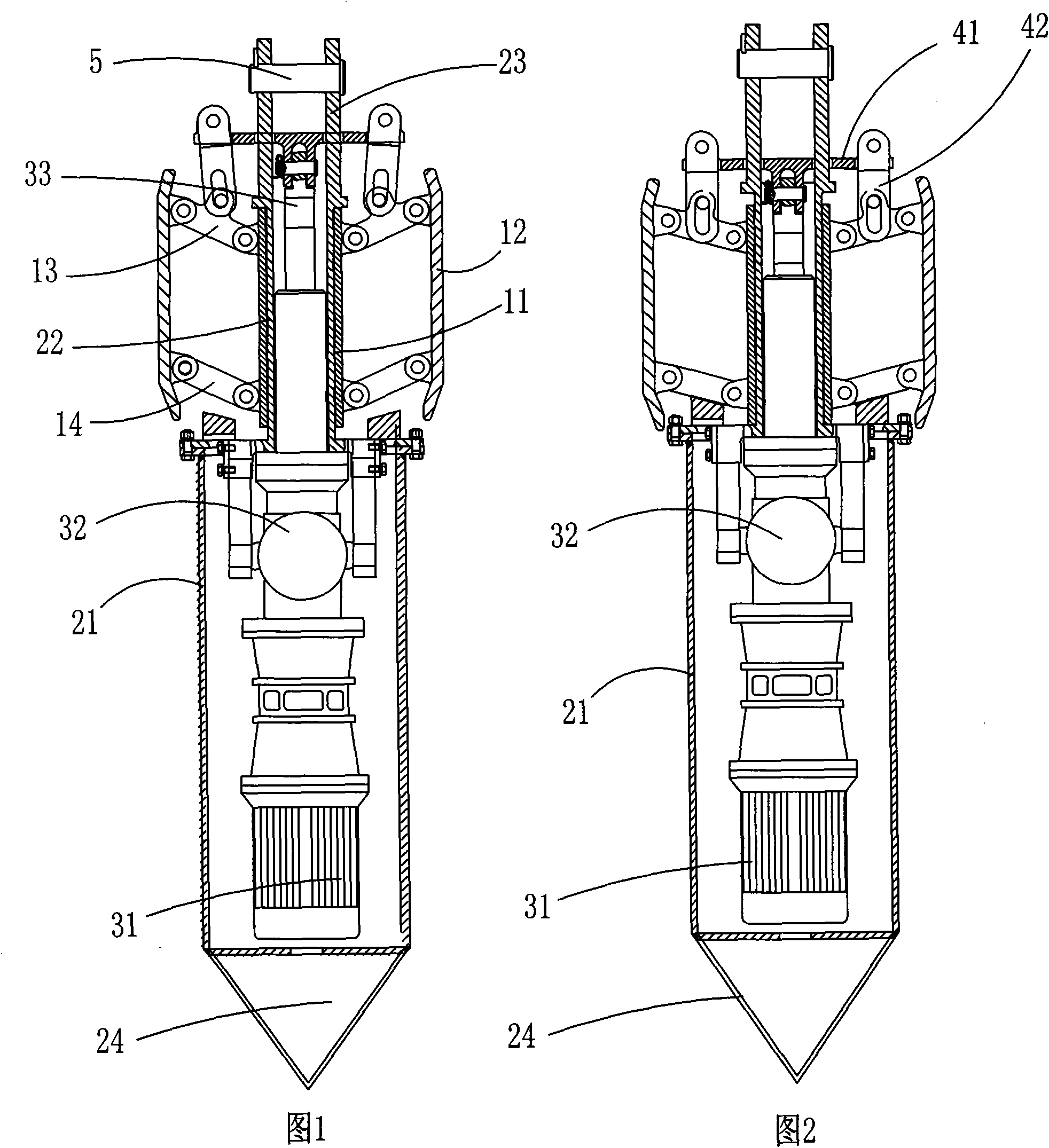
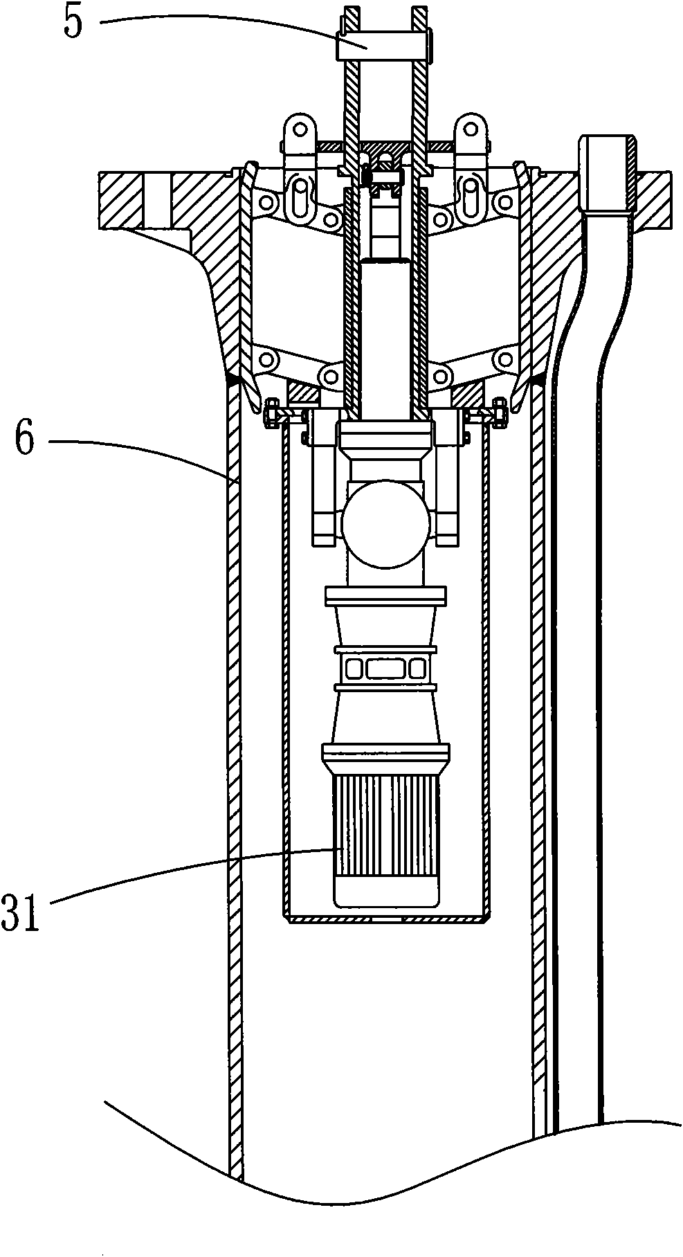
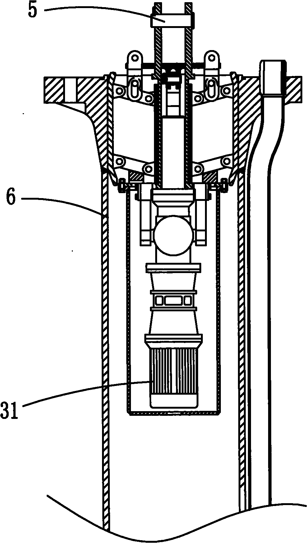
[0018] see figure 1 , figure 2 and image 3 , the structure of this embodiment is set to:

[0019] With the piston ejector rod 33 as the center, three sets of four-bar linkages are evenly distributed on the outer circumference;

[0020] The central rod 11 of the four-bar linkage mechanism is fixedly connected with the frame, and the outer rod is set as a brace 12, and the brace 12 and the central rod 11 are hinged with an upper link 13 and a lower link 14 parallel to each other;

[0021] The frame is a cylinder, in the frame cylinder, a motor 31 and an electric push rod 32 driven by the motor 31 are fixedly installed in the lower cylinder 21 below the four-bar linkage mechanism; The outside of the cylinder body 22 is the center rod 11 which is arranged around it, and the inside of the cylinder body is the piston push rod 33 which can slide axially in the middle section cylinder body 22; The hook shaft 5 for lifting is fixedly arranged on the top of the lifting rod 23;

...


PUM


Abstract

The invention discloses a shaft-well drill rod lifter, which is characterized in that: three groups of four-bar mechanisms are uniformly distributed on the outer circumference by using a piston top rod as the center; and central rods of the four-bar mechanisms are fixedly connected with a rack, outside rods are provided with supporting plates, and the supporting plates and the central rods are hinged by an upper connecting rod and a lower connecting rod in parallel. Because the four-bar mechanisms are adopted, the lifter enables the supporting plates to support the inner wall of a drill rod by means of friction force so as to realize lifting; and meanwhile, the supporting plates can be separated from the inner wall of the drill rod by using an electric push rod through a pull disc so that the lifter is separated from the drill rod. The process is quick, safe and reliable, and can greatly improve the work efficiency.

Description

technical field [0001] The invention relates to a hoisting device for lifting the drill pipe of a shaft drilling rig. Background technique [0002] Shaft drilling rigs are used for drilling large diameter, deep shafts. In complex formations, due to the instability of the drilling process and the formation, in order to ensure the safety of the drilled wellbore, the drilling tool must be lifted every 5 to 7 days to prevent unsafe factors such as wellbore necking and sticking. In this process, the time for connecting and unloading drill pipes accounts for more than 15% of the entire drilling period. In the prior art, the lifting of the drill pipe is manually installed and unloaded, which is slow in speed and labor-intensive. Contents of the invention [0003] The purpose of the present invention is to avoid the disadvantages of the above-mentioned prior art, and to provide a safe and reliable drill pipe lifter for a shaft drilling rig, so as to improve drilling efficiency. ...

Claims


Application Information

Patent Timeline
Patent Type & Authority Applications(China)
IPC IPC(8): E21B19/02
Inventor 丁明王占军金汝励蔡鑫
Owner CHINA COAL SPECIAL DRILLING ENG GROUP
Why Eureka
Try Eureka