Compression spring
A compression spring and helical body technology, applied in the field of compression springs, can solve problems that are not suitable for large areas, large pressure external loads, etc.
Inactive Publication Date: 2010-10-20
周成水
View PDF0 Cites 0 Cited by
- Summary
- Abstract
- Description
- Claims
- Application Information
AI Technical Summary
Problems solved by technology
However, the existing spring shape is not suitable for large area and large pressure external load
Method used
View moreImage
Smart ImageViewing Examples

Examples
Embodiment Construction
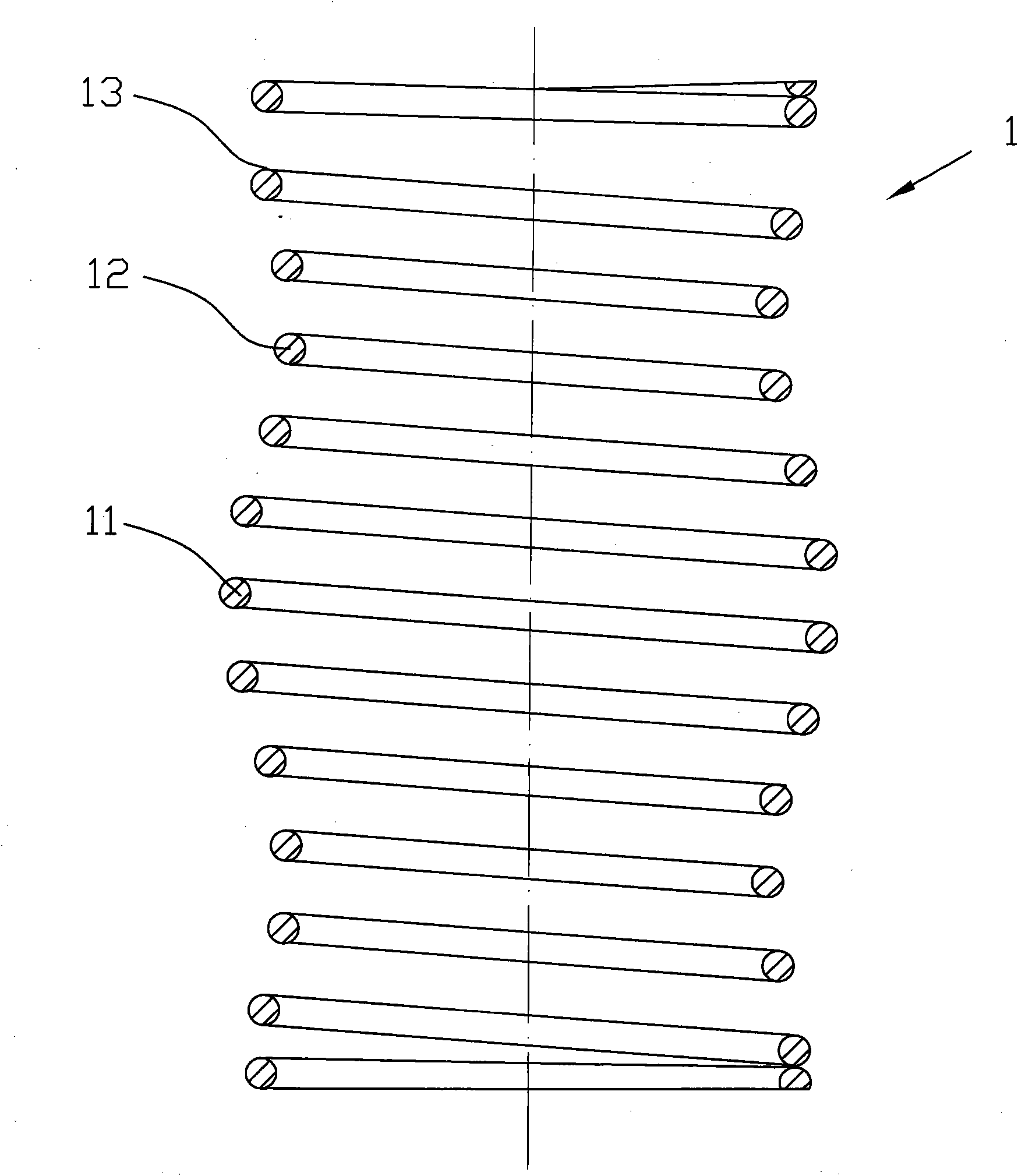
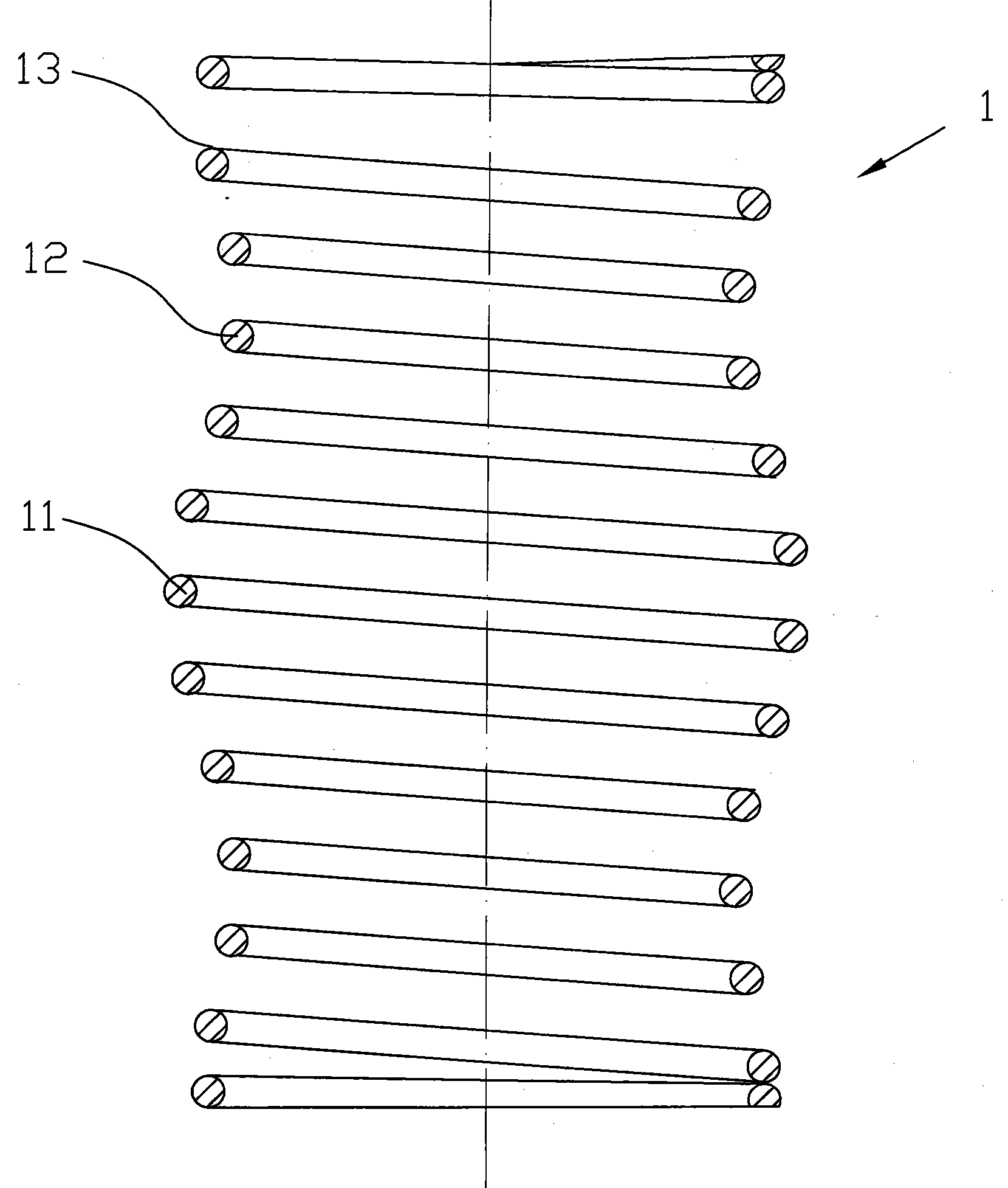
[0009] Such as figure 1 As shown, it is an embodiment of a compression spring of the present invention, which includes a spiral body 1, and the spiral body includes a circular arc convex section 11 in the middle, and an arc is provided between the circular arc convex section and the two ends of the spiral body. Concave section 12. The cylindrical section 13 is between the concave section of the circular arc and the two ends of the screw body.
Login to View More PUM
 Abstract
The invention discloses a compression spring, which comprises a spiral body, wherein the middle part of the spiral body is provided with an arched protruded section; arched sunken sections are arranged between the arched protruded section and each end of the spiral body respectively; and cylindrical sections are arranged between each arched sunken section and the corresponding ends of the spiral body respectively. Due to the adoption of the technical scheme, the compression spring can be adapted to large-area and high-pressure external load.
Description
technical field [0001] The invention relates to a compression spring. Background technique [0002] The compression spring is a helical spring that bears the pressure. The cross-section of the material used is mostly circular, and it is also made of rectangular and multi-strand steel coils. The spring is generally of equal pitch. The shapes of the compression spring are: cylindrical, conical Shape, convex and concave, and a small amount of non-circular, etc., to meet the needs of different working conditions. There is a certain gap between the coils of the compression spring. When the external load is applied, the spring shrinks and deforms, storing deformation energy. However, the existing spring shape is not suitable for large area and large pressure external load. Contents of the invention [0003] The technical problem to be solved by the present invention is to provide a compression spring adaptable to large area and large pressure external load. [0004] In order ...
Claims
Login to View More Application Information
Patent Timeline
 IPC IPC(8): F16F1/04
Inventor 周成水
Owner 周成水
Features
- R&D
- Intellectual Property
- Life Sciences
- Materials
- Tech Scout
- Unparalleled Data Quality
- Higher Quality Content
- 60% Fewer Hallucinations
Learn More Browse by: Latest US Patents, China's latest patents, Technical Efficacy Thesaurus, Application Domain, Technology Topic, Popular Technical Reports.
© 2025 PatSnap. All rights reserved.Legal|Privacy policy|Modern Slavery Act Transparency Statement|Sitemap|About US| Contact US: help@patsnap.com