Umbrella light

a technology for umbrellas and umbrellas, applied in umbrellas, gyms, clubs, etc., can solve the problem that no umbrella attachment clip is included to easily attach a solar panel to the outside fabric of a standard umbrella, and achieve the effect of convenient attachmen

Inactive Publication Date: 2007-10-18
BLATECKY ROBERT
View PDF11 Cites 77 Cited by
  • Summary
  • Abstract
  • Description
  • Claims
  • Application Information

AI Technical Summary

Benefits of technology

[0009] Another object of the invention is to provide a fully assembled umbrella light that can be easily attached, by means of a single torsion spring, at any desired height to the support pole of an outdoor umbrella.
[0010] Another object of the invention is to provide an umbrella light whose color output can be balanced using a combination of independently adjustable cool white and amber LED's.
[0011] A further object of the invention is to provide an umbrella light that allows easy attachment of a solar panel to the fabric portion of an umbrella and includes an electrical cable that feeds power to rechargeable batteries located within the light housing.

Problems solved by technology

None of the above patents or applications describes a way to easily attach an umbrella light to an existing standard umbrella in a way which universally requires no assembly, tools or closure buckles.
None include a combination of independently controlled cool white and amber LED's for optimum color balance, and none uses a choice of AA or C type batteries.
Finally, none includes an umbrella attachment clip to easily attach a solar panel to the outside fabric of a standard umbrella.

Method used


Image

  • Umbrella light
  • Umbrella light
  • Umbrella light

Examples


Embodiment Construction

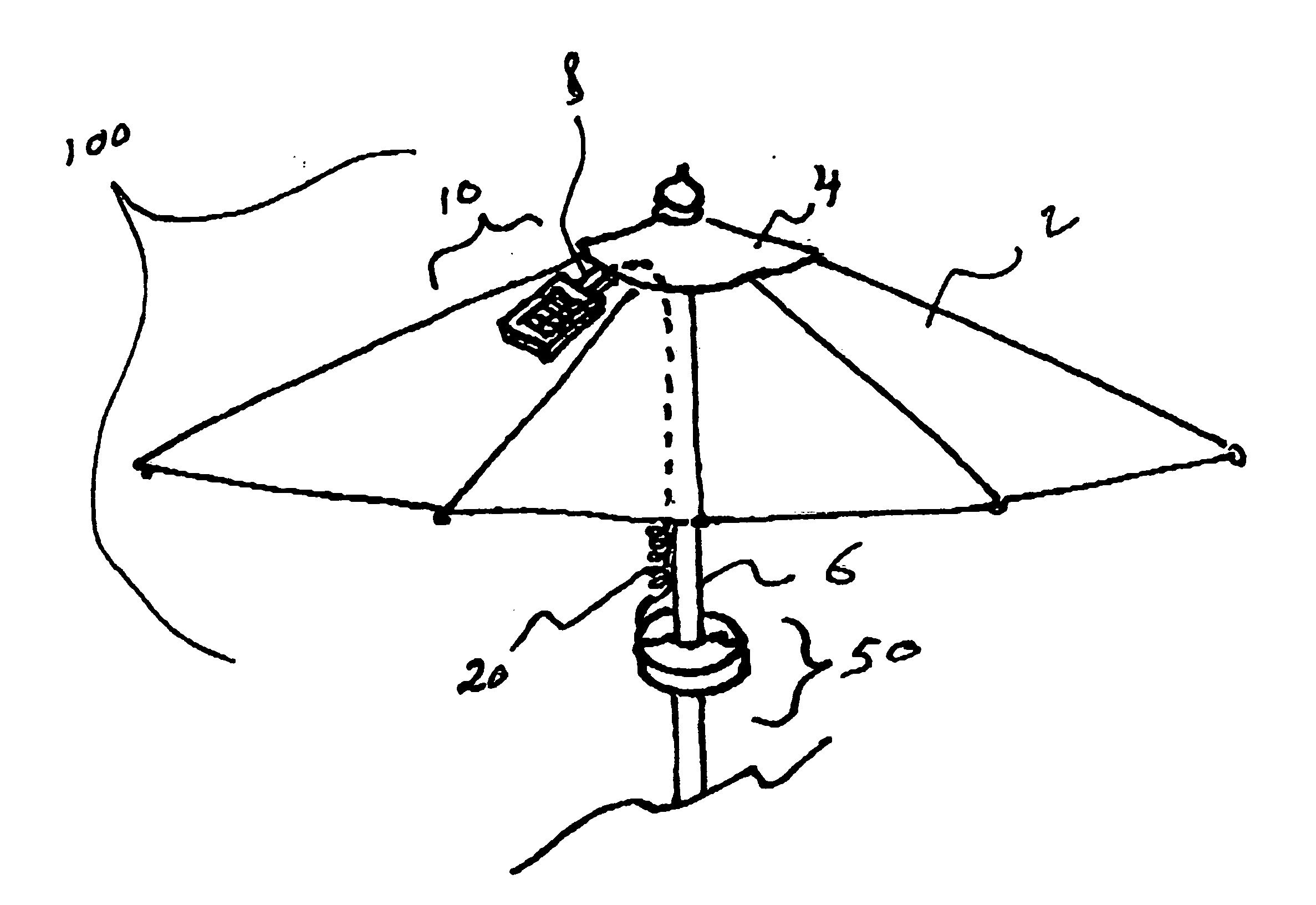
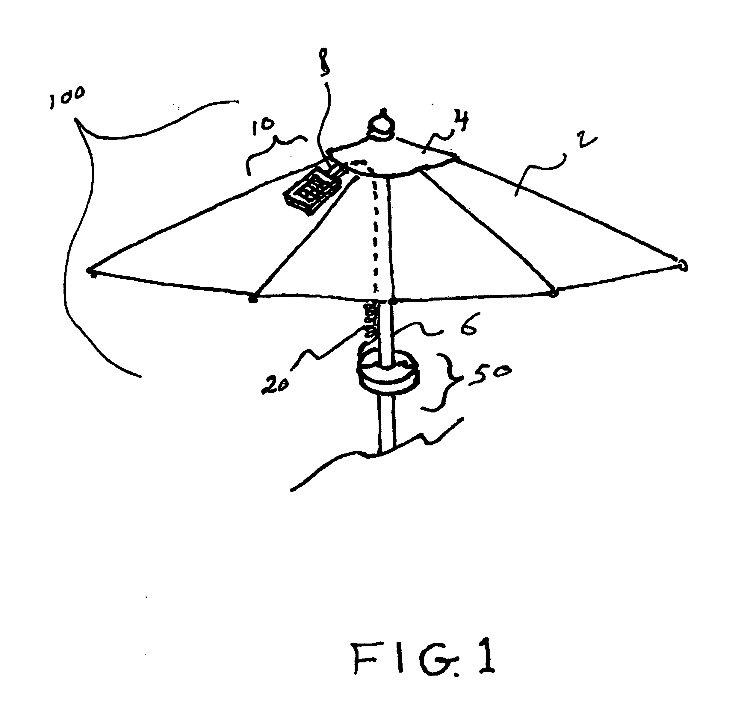
[0026] Detailed descriptions of the preferred embodiment are provided herein. It is to be understood, however, that the present invention may be embodied in various forms. Therefore, specific details disclosed herein are not to be interpreted as limiting, but rather as a basis for the claims and as a representative basis for teaching one skilled in the art to employ the present invention in virtually any appropriately detailed system, structure or manner. Referring now to FIG. 1 we see a perspective view of the invention 100 attached to a standard umbrella 2. It consists of housing 50 that is doughnut or other shaped so that it can attach to a standard umbrella pole 6. A pair of coiled insulated wires 20 travel from the housing 50 to a solar panel 10 located on the outside of the umbrella fabric and held in place by solar panel clip 8. The coiled nature of the insulated wires allows for adjustment in height of the light housing 50 without the need for additional wire retaining ties ...


PUM


Abstract

An umbrella light that can be attached to most common outdoor umbrellas using a pair of opposing semi-circular housings permanently joined by a hinge and a single torsion spring. The spring is biased inward towards the central aperture thereby creating an effective means of attachment. Within the housings are a plurality of LED's, batteries and an optional IC charging monitor. An optional solar panel is attached to the umbrella via an attachment clip. All components are wired in a standard way. The housings each include a centrally located hemispherical cut out area creating a circular aperture to allow for attachment to the support pole of a standard outdoor umbrella, and a self contained flat clip for non-pole use. The floor of the housings has a plurality of apertures that allow light from the enclosed LED's to exit.

Description

CROSS REFERENCE TO RELATED APPLICATIONS [0001] Not Applicable STATEMENT REGARDING FEDERALLY SPONSORED RESEARCH OR DEVELOPMENT [0002] Not Applicable DESCRIPTION OF ATTACHED APPENDIX [0003] Not Applicable BACKGROUND OF THE INVENTION [0004] This invention relates generally to the field of outdoor umbrella accessories and more specifically to an umbrella light. [0005] Outdoor umbrellas have been used in residential and commercial settings for many years. Traditionally they serve the purpose of creating comfortable shade in an otherwise sunny, hot environment. However, in recent times it has also become popular to use outdoor umbrellas during evening activities such as having an outdoor dinner or other evening event. It is desirable to have a source of illumination during such evening events. [0006] To this end, the addition of a lighting fixture to the underside of an umbrella, which could shine light down on a table and surrounding people or other objects would be desirable. Another de...

Claims


Application Information

Patent Timeline
Patent Type & Authority Applications(United States)
IPC IPC(8): A45B3/02
CPCA45B2200/1027A45B3/04
Inventor BLATECKY, ROBERT
Owner BLATECKY ROBERT
Why Eureka
Try Eureka