Torque limited decoupler

a decoupler and torque limit technology, applied in the direction of couplings, slip couplings, gearings, etc., can solve the problem of reducing the long-term durability of decouplers

Active Publication Date: 2010-08-03
LITENS AUTOMOTIVE INC
View PDF21 Cites 77 Cited by
  • Summary
  • Abstract
  • Description
  • Claims
  • Application Information

AI Technical Summary

Benefits of technology

[0006]The disadvantages of the prior art may be overcome by providing a decoupler that prevents torques above a predetermined torque value from overstressing the torsion spring.

Problems solved by technology

However, in certain applications in which the engine has an aggressive start profile or during conditions of rapid acceleration during a wide open throttle shift, the torques transmitted will over-stress the torsion spring reducing long term durability of the decoupler.

Method used


Image

  • Torque limited decoupler
  • Torque limited decoupler
  • Torque limited decoupler

Examples


first embodiment

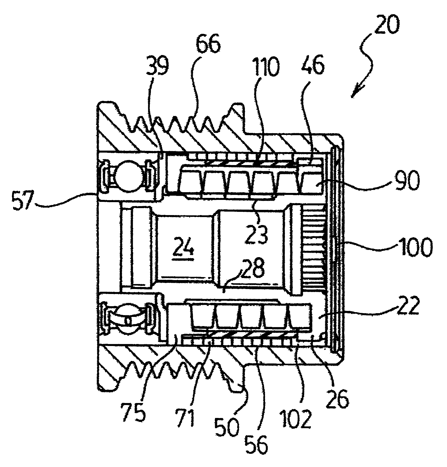
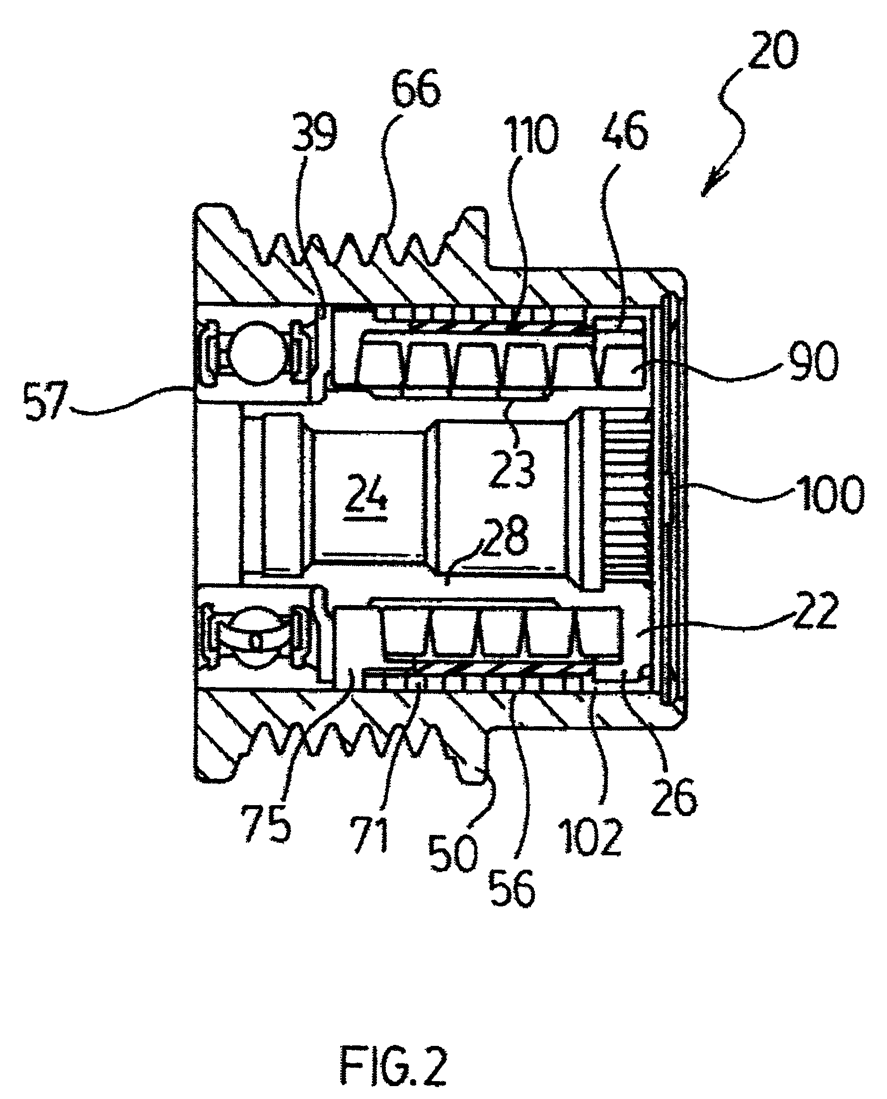
[0026]Referring to FIGS. 2 and 3, the decoupler assembly 20 generally includes a hub 22, a pulley 50, a clutch assembly 70, a torsion spring 90 and a torque limiter 110. In the first embodiment, the torque limiter 110 is preferably a sleeve.

[0027]Hub 22 has a generally cylindrical body 28 having an axially extending bore 24 and a flange 26 at one end thereof. Flange 26 has a generally helical first slot 46 on an inner face thereof. Since the slot 46 is helical, the slot 46 will have a step. The bore 24 is configured for fixedly securing the hub 22 to a drive shaft extending from the belt driven accessory 16.

[0028]A pulley 50 is rotatably journaled to the hub 22. A ball bearing assembly 57 is coupled between the pulley 50 and the hub 22 at a distal end while a bushing journal 102 mounts the pulley 50 on the circumferential face of flange 26. The bearing assembly 57 is conventional comprising an inner race, an outer race and a plurality of ball bearings rollingly engaged therebetween....

second embodiment

[0035]the sleeve is illustrated in FIG. 8. Torque limiter 110′ is a closed metal ring. The metal ring would only expand to a relatively small degree, directly limiting outward expansion of the torsion spring 90.

third embodiment

[0036]the sleeve is illustrated in FIG. 9a. Torque limiter 110″ has a plurality of axially elongate openings 116 spaced circumferentially spaced about the torque limiter 110″. The openings 116 enable the grease lubricant to travel outwardly to the clutch spring 71.

[0037]An alternative third embodiment of the sleeve is illustrated in FIG. 9b. The torque limiter 110* has a series of circumferentially spaced openings 116* and 117. Preferably, openings 116* are elongate and openings 117 are circular and spaced in a regular pattern, resembling dimples on a golf ball. Additionally, torque limiter 110* has an integrally extending radial flange 119 that acts a thrust bearing.

[0038]A cap 100 is attached to the end of pulley 50 for preventing contaminants from entering the decoupler assembly 20 and for retaining the lubricant within the decoupler assembly 20.

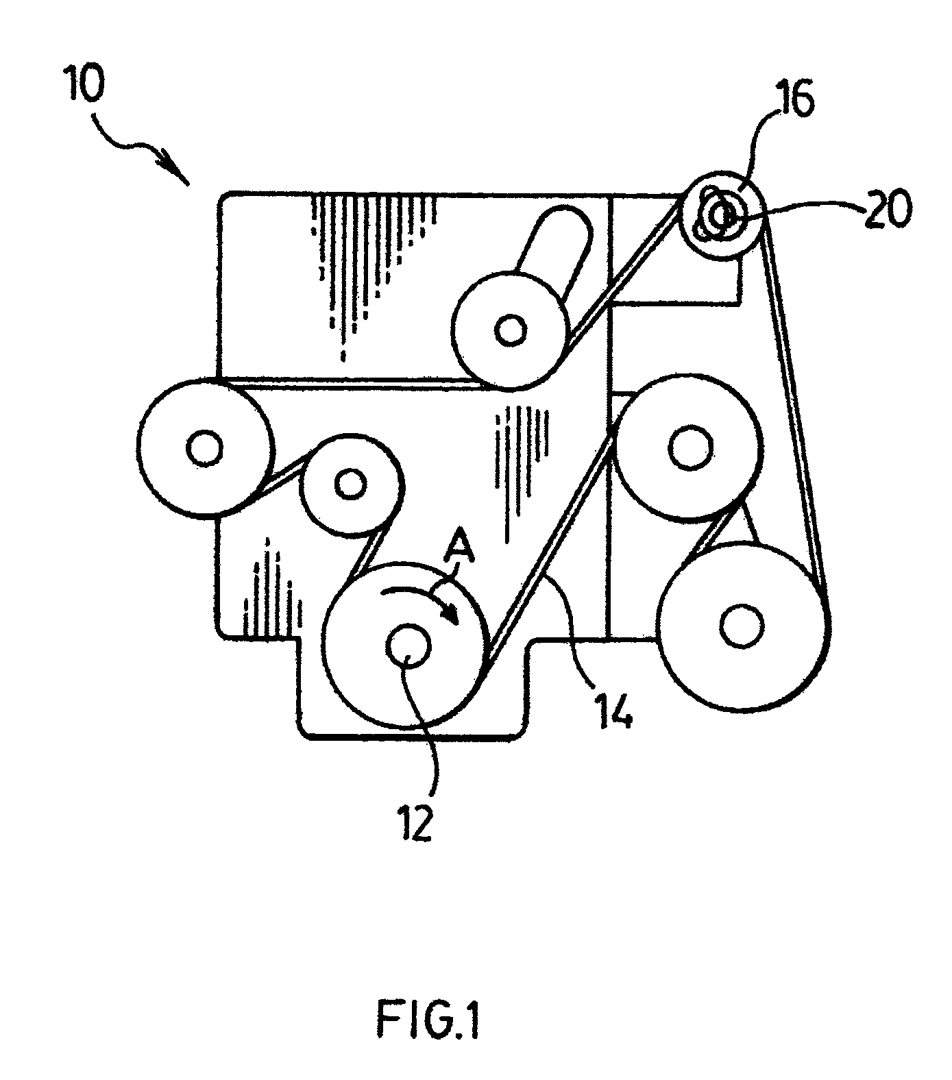
[0039]In operation, the engine 10 is started and the pulley 50 is accelerated and rotated in a driven direction (designated by arrow A i...


PUM


Abstract

A decoupler assembly is provided for allowing an alternator to be rotatably driven by a serpentine belt in an engine of an automotive vehicle and for allowing the speed of the belt to oscillate relative to the alternator. A hub is fixedly carried by a drive shaft from the alternator for rotation therewith. A pulley is rotatably journaled to the hub by a ball bearing assembly. A bare, helical clutch spring is operatively coupled between the hub and pulley for transferring rotational movement from the pulley to the hub during acceleration of the pulley relative to the hub by the serpentine belt and for allowing the hub to overrun the pulley during deceleration of the pulley relative to the hub. A torque limiter, preferably a spring or sleeve, is wrapped about the torsion limiting outward expansion of the torsion isolating the torsion spring from torques above a predetermined limit.

Description

[0001]This application is a 371 of PCT / CA06 / 00129, filed Feb. 3, 2006, which claims the benefit of 60 / 649,520, filed on Feb. 3, 2005.FIELD OF THE INVENTION[0002]The present invention relates to a belt drive assembly for driving belt driven accessories in an engine of an automotive vehicle, and more particularly, to a decoupling mechanism for allowing the belt driven accessories to operate temporarily at a speed other than the endless drive assembly and for isolating the torsion spring from excessive torques.BACKGROUND OF THE INVENTION[0003]An automotive vehicle engine transfers a portion of the engine output to a plurality of belt driven accessories utilizing an endless serpentine belt. Typically, each component includes an input drive shaft and a pulley coupled to a distal end of the drive shaft for driving engagement with the belt. An example of such a belt driven accessory is an alternator.[0004]A decoupler is operatively coupled between the pulley and the alternator to allow the...

Claims


Application Information

Patent Timeline
Patent Type & Authority Patents(United States)
IPC IPC(8): F16D41/20
CPCF16D7/022F16D41/203F16D43/211F16H55/36E05Y2201/49E05Y2800/22F16D41/206F16D41/20F16D7/02F16H7/00F02B67/06
Inventor ANTCHAK, JOHN R.KAIPONEN, MARKGRANIERO, ROBERT
Owner LITENS AUTOMOTIVE INC
Why Eureka
Try Eureka