Electromagnetic valve

A solenoid valve and solenoid coil technology, applied in valve details, valve devices, valve operation/release devices, etc., can solve the problems of complex structure of porous parts and no consideration of refrigerant circulation and diffusion, etc., to ensure the passage area and reduce the Effect of small pressure change and noise reduction

Active Publication Date: 2013-10-16
ZHEJIANG SANHUA INTELLIGENT CONTROLS CO LTD
View PDF2 Cites 1 Cited by
  • Summary
  • Abstract
  • Description
  • Claims
  • Application Information

AI Technical Summary

Problems solved by technology

[0007] However, the conventional solenoid valve of Patent Document 1 has a porous member that straddles the shoulder portion and the wall portion of the valve portion and is in contact with the segment portion. Therefore, the porous member needs to have a thick portion and a thin portion, so there is a problem that the structure of the porous member is complicated.
[0008] In addition, the conventional solenoid valve of Patent Document 2 does not take into account the problem of gradually flowing and diffusing the inflowing refrigerant to the porous member when subdividing the air bubbles.

Method used


Image

  • Electromagnetic valve
  • Electromagnetic valve
  • Electromagnetic valve

Examples


Embodiment Construction

[0026] Embodiments of the present invention will be described in detail below with reference to the drawings.

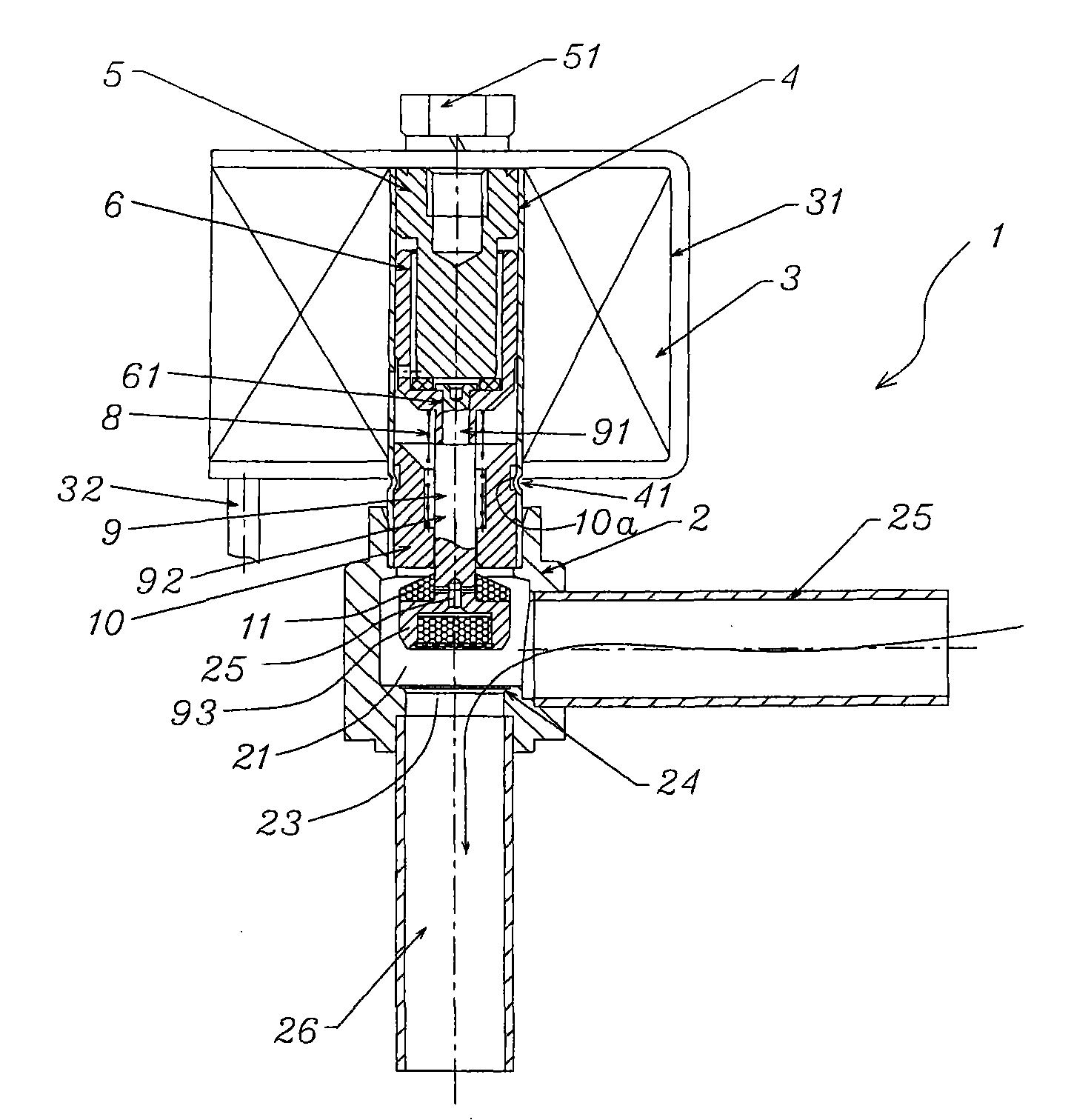
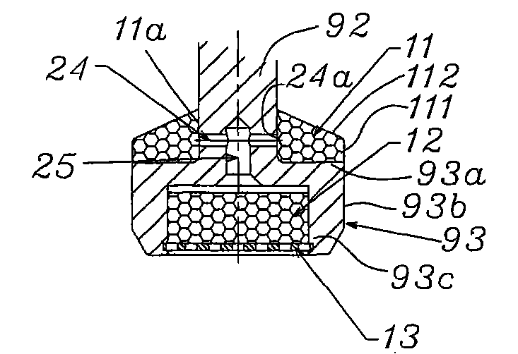
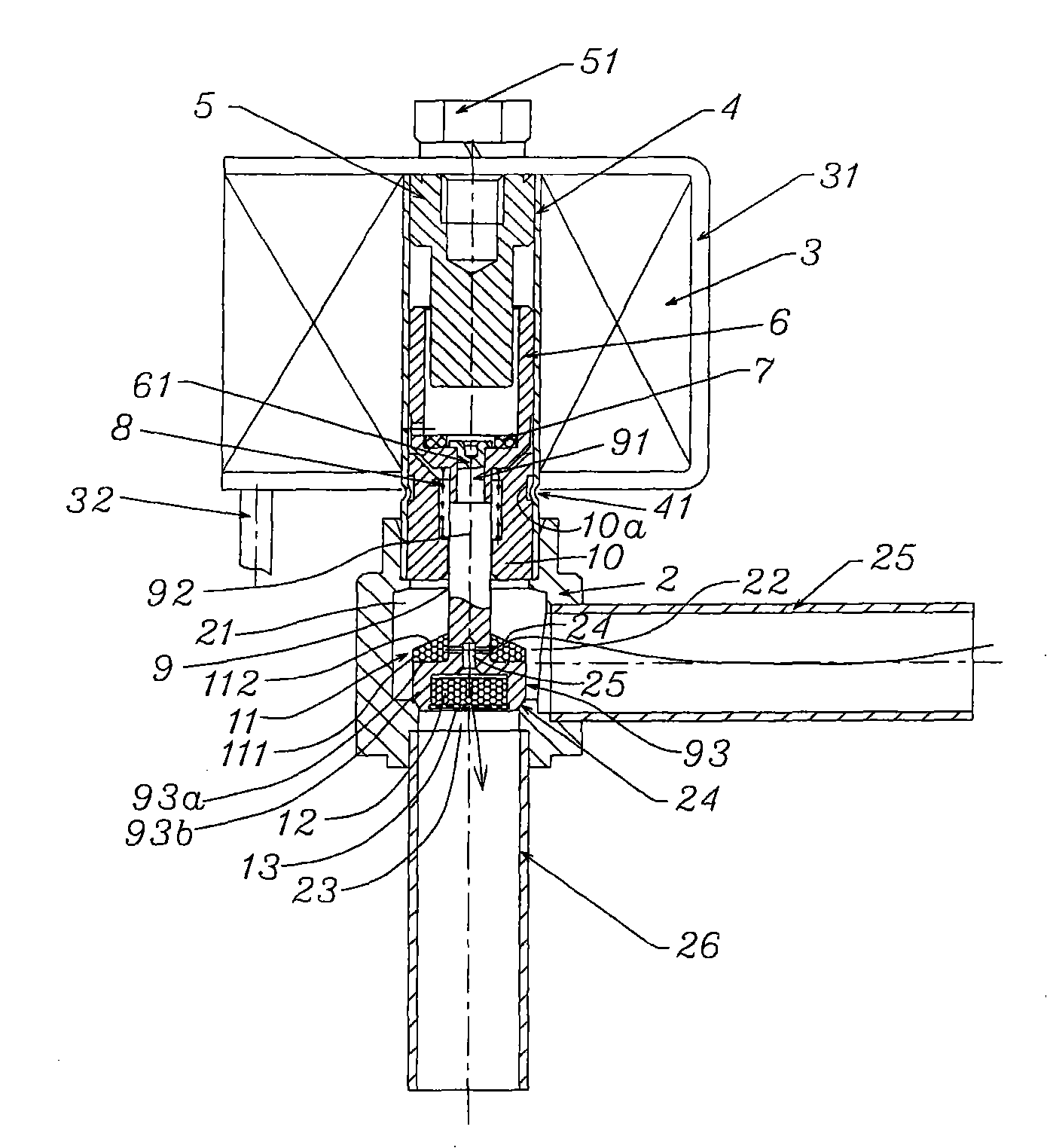
[0027] figure 1 It is a sectional view of the first embodiment of the solenoid valve of the present invention; figure 2 for figure 1 Enlarged view of the main parts of the spool; image 3 for figure 1 The state diagram of the solenoid valve when the valve is closed. figure 1 The solenoid valve 1 includes: on the valve body 2 with the valve chamber 21, a tubular casing part 4 is erected (for example, fixed by welding), and the electromagnetic coil 3 arranged on the outer periphery of the casing part 4 is fixed on the casing part. 4, the cylindrical attractor 10 inside, the core iron 6 disposed inside the sleeve part 4 facing the attractor 10, and the core iron 6 connected and movable in the axial direction of the sleeve part 4 The cylindrical valve core 9, the inflow side passage 22 and the outflow side passage 23 formed on the valve body 2 and communicated with...


PUM


Abstract

The invention provides an electromagnetic valve. A valve core can be close to or far away from a valve seat part formed on a valve body through an electromagnetic coil, the valve body is provided with an inflow side channel and an outflow side channel, the valve core is provided with a conical first porous member and a disk-shaped second porous member, wherein the conical first porous member is arranged on the periphery of the valve core opposite to the inflow side channel, and the disk-shaped second porous member is kept in the valve core opposite to the outflow side channel. In the electromagnetic valve, because the periphery of the valve core formed to be a refrigerant inflow side is configured with the conical first porous member, the first porous member can subdivide air bubbles in refrigerants by utilizing a reduced conical part facing to the valve core, and the inflow air-liquid two-phase refrigerants can gradually diffuse to the porous member, which can diffusedly pass through the porous member. As a result, the first porous member can also be used as a constitution member for inhibiting pressure changes while being used as a constitution member for subdividing the air bubbles of the refrigerants.

Description

technical field [0001] The invention relates to a solenoid valve for an air conditioner. Background technique [0002] Air conditioners generally switch between cooling and heating by reversing the flow of refrigerant to the outdoor heat exchanger and the indoor heat exchanger. [0003] In the refrigeration cycle system of the air conditioner, in order to perform dehumidification operation, the indoor heat exchanger is divided into two types for cooling and reheating, and the dehumidification operation is performed by an expander installed between the two. [0004] When the solenoid valve is used as an expander to throttling, the refrigerant will generate flow noise along with its throttling action, and when the refrigerant generates flow sound, noise will be formed. [0005] In order to prevent the generation of refrigerant flow sound, for example, refer to Patent Document 1 of JP-A-2003-156269. In this prior art, a first member for subdividing air bubbles is provided on t...

Claims


Application Information

Patent Timeline
Patent Type & Authority Patents(China)
IPC IPC(8): F16K31/06F25B41/06
Inventor 严卫林
Owner ZHEJIANG SANHUA INTELLIGENT CONTROLS CO LTD
Why Eureka
Try Eureka