Air conditioning unit provided with flooded shell-tube heat exchanger

A technology for shell and tube heat exchangers and air conditioning units, which is applied in indirect heat exchangers, heat exchanger types, fixed tubular conduit assemblies, etc., can solve problems such as energy waste, damage to compressors, etc. The effect of preventing hydraulic shock accidents and increasing the amount of compression

Inactive Publication Date: 2017-05-31
GREE ELECTRIC APPLIANCES INC
View PDF16 Cites 7 Cited by
  • Summary
  • Abstract
  • Description
  • Claims
  • Application Information

AI Technical Summary

Problems solved by technology

[0006] Therefore, the technical problem to be solved by the present invention is to overcome the refrigerant buffered in the gas-liquid separator of the air-conditioning unit with the flooded shell-and-tube heat exchanger in the prior art, which not only cannot be fully utilized and causes energy waste, but also Excessive buffer capacity causes the compressor to suck in a large amount of refrigerant liquid, resulting in liquid shock damage to the compressor, thereby providing a way to make full use of the refrigerant buffered in the gas-liquid separator to reduce energy waste, while avoiding compressor suction caused by excessive buffer capacity Air conditioning units with flooded shell and tube heat exchangers with flooded shell and tube heat exchangers due to flooding of refrigerant liquid resulting in liquid hammer damage to the compressor

Method used


Image

  • Air conditioning unit provided with flooded shell-tube heat exchanger

Examples


Embodiment Construction

[0038]The technical solutions of the present invention will be clearly and completely described below in conjunction with the accompanying drawings. Apparently, the described embodiments are some of the embodiments of the present invention, but not all of them. Based on the embodiments of the present invention, all other embodiments obtained by persons of ordinary skill in the art without making creative efforts belong to the protection scope of the present invention.

[0039] In addition, the technical features involved in the different embodiments of the present invention described below may be combined with each other as long as there is no conflict with each other.

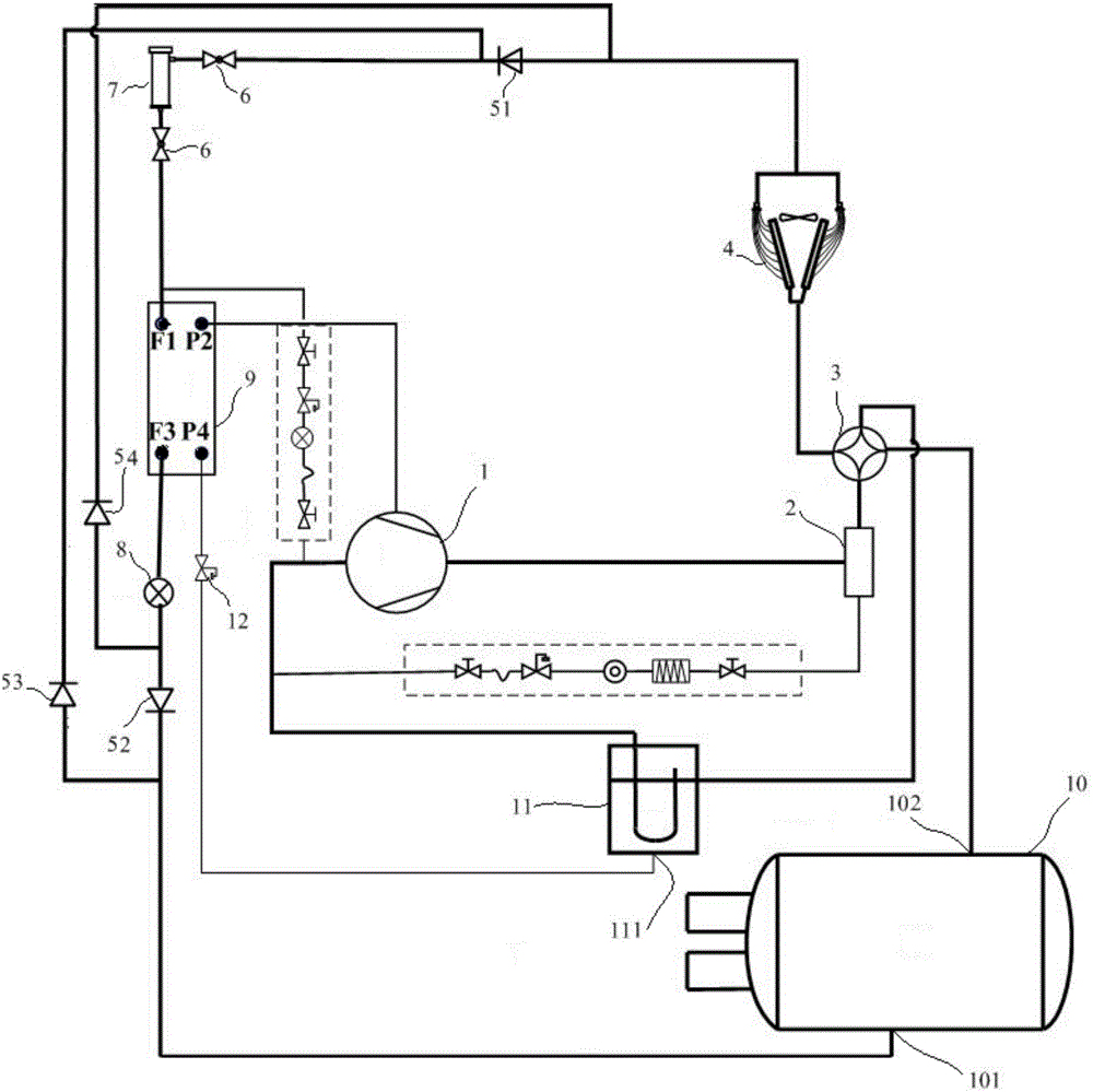
[0040] like figure 1 As shown, this embodiment provides an air conditioning unit with a flooded shell-and-tube heat exchanger, including a compressor 1, a first heat exchanger 4, a flooded shell-and-tube heat exchanger 10, a throttling element 9, a gas Liquid separator 11 and two-way heat exchanger 8. Wherei...


PUM


Abstract

The invention provides an air conditioning unit provided with a flooded shell-tube heat exchanger. The air conditioning unit comprises a compressor, a first heat exchanger communicated with an outflow end of the compressor, the flooded shell-tube heat exchanger, a throttling element connected between the first heat exchanger and the flooded shell-tube heat exchanger, an air-liquid separator and a two-way heat exchanger, wherein a first end of the tube pass of the flooded shell-tube heat exchanger is connected with a first end of the first heat exchanger, and a second end of the tube pass of the flooded shell-tube heat exchanger is connected with an inflow end of the compressor; the air-liquid separator is at least connected between the second end of the tube pass of the flooded shell-tube heat exchanger and the inflow end of the compressor; the first end of the first heat exchanger and the second end of the tube pass of the flooded shell-tube heat exchanger are connected with a first heat exchange pipeline of the two-way heat exchanger, one end of a second heat exchange pipeline of the two-way heat exchanger is connected with an auxiliary road end of a communication liquid phase of the air-liquid separator, and the other end of the second heat exchange pipeline is communicated with a middle air supplementing port of the compressor. Cached refrigerant liquid in the air-liquid separator can be reduced, and liquid impact accidents caused by the fact that the compressor inhales a lot of refrigerant liquid are prevented.

Description

technical field [0001] The invention relates to the technical field of heat pump systems, in particular to an air conditioning unit with a flooded shell-and-tube heat exchanger. Background technique [0002] The evaporator of an air conditioning unit usually includes a flooded shell and tube heat exchanger and a dry shell and tube heat exchanger. [0003] Compared with the dry shell and tube heat exchanger, the flooded shell and tube heat exchanger has a much larger refrigerant charge. Because of the large amount of refrigerant charge, the heat transfer between water and refrigerant approaches a small temperature difference, and the heat transfer efficiency is relatively high, which has a significant advantage in improving performance. However, due to the large amount of refrigerant filling in the flooded shell and tube, and the liquid refrigerant in the heat exchanger, the refrigerant filling volume of the entire air conditioning system is much larger than that of the dry ...

Claims


Application Information

Patent Timeline
Patent Type & Authority Applications(China)
IPC IPC(8): F24F5/00F24F13/30F25B39/00F28D7/00F25B13/00F25B41/06F25B43/00F25B41/04F25B31/00F25B41/20F25B41/31F25B41/37
CPCF24F5/0003F24F13/30F25B13/00F25B31/004F25B39/00F25B43/00F28D7/00F25B41/22F25B41/31
Inventor 钟海玲程琦刘思源黄凯亮
Owner GREE ELECTRIC APPLIANCES INC
Why Eureka
Try Eureka