Backlight module

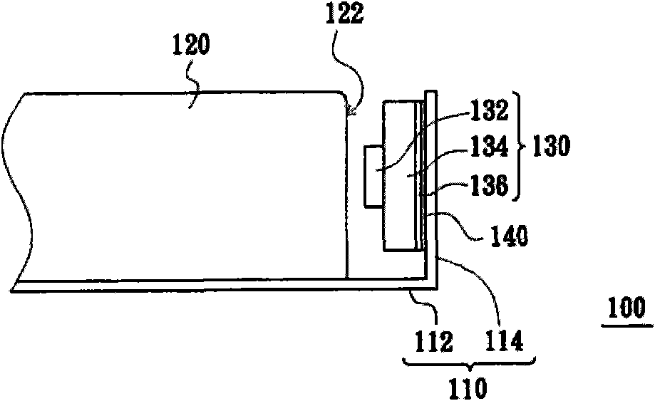
A backlight module and light-incident surface technology, applied in the direction of optics, light guides, light sources, etc., can solve the problems that the adhesive layer 140 is easy to remain, the circuit board 134 cannot be used again, the circuit board 134 and the side wall 114 are easily damaged and deformed, and achieve The effect of easy disassembly

Inactive Publication Date: 2010-10-20
CORETRONIC (SUZHOU) CO LTD
View PDF0 Cites 8 Cited by
  • Summary
  • Abstract
  • Description
  • Claims
  • Application Information

AI Technical Summary

Problems solved by technology

However, since the light emitting device 130 is attached to the side wall 114, after the light emitting device 130 is torn off from the side wall 114, the adhesive layer 140 is likely to remain on the side wall 114, and the circuit board 134 and the side wall 114 are easily damaged and deformed. , thereby making the circuit board 134 unusable again

Method used


Image

  • Backlight module
  • Backlight module
  • Backlight module

Examples


Embodiment Construction

[0043] The aforementioned and other technical contents, features and effects of the present invention will be clearly presented in the following detailed description of the embodiments with reference to the accompanying drawings. The directional terms mentioned in the following embodiments, such as: up, down, left, right, front or back, etc., are only directions referring to the attached drawings. Accordingly, the directional terms are used to illustrate and not to limit the invention.

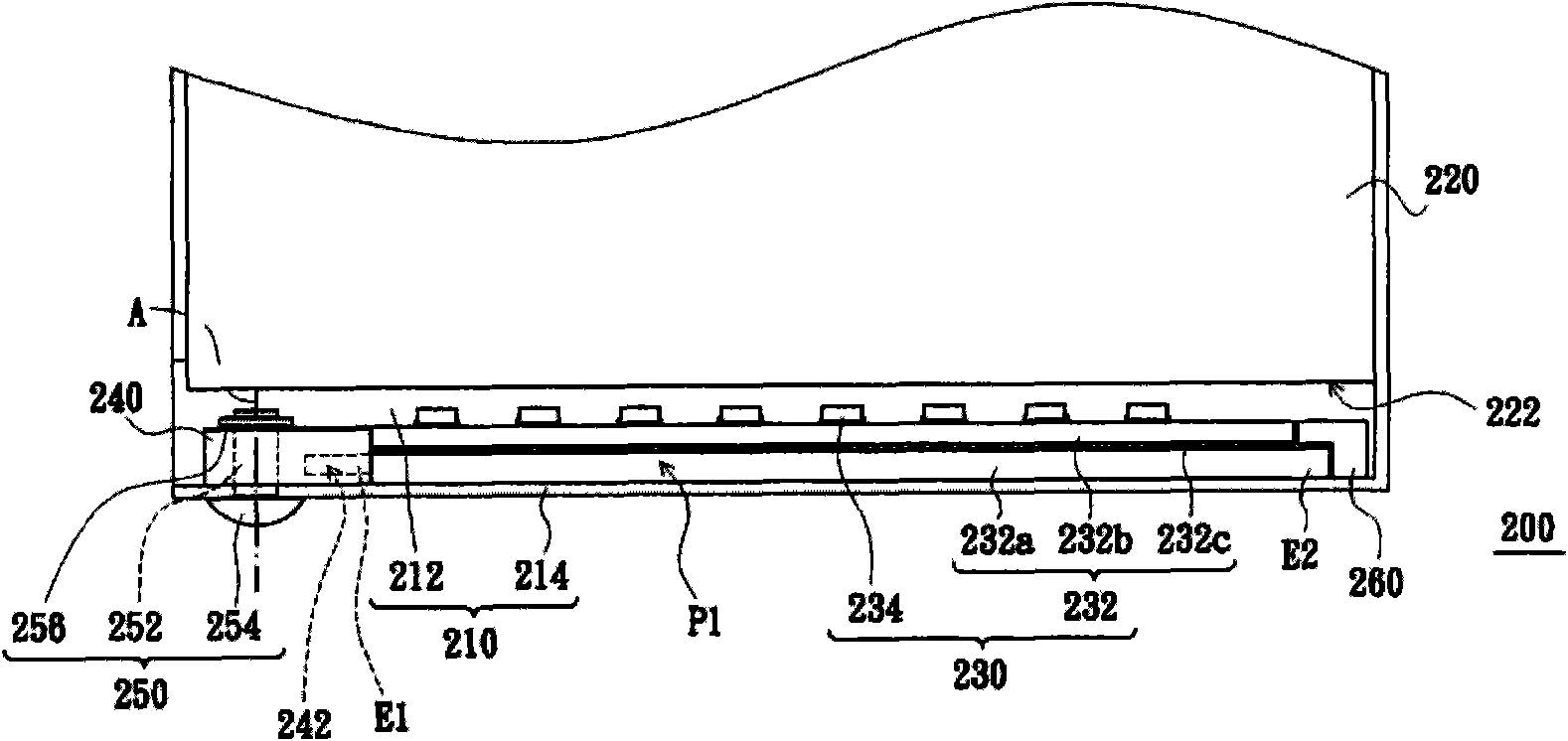
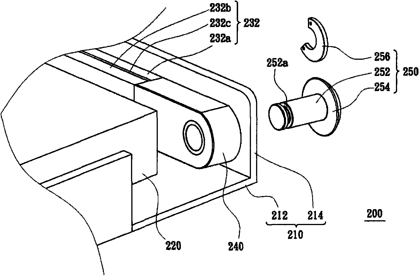
[0044] figure 2 A schematic top view of a backlight module according to an embodiment of the present invention is shown. image 3 draw figure 2 The three-dimensional exploded schematic diagram of some components of the backlight module. Figure 4 draw figure 2 A three-dimensional schematic diagram of the light-emitting device. Please refer to figure 2 , image 3 and Figure 4 , the backlight module 200 of this embodiment includes a base 210 , a light guide plate 220 , a light emitt...


PUM


Abstract

The invention discloses a backlight module, which comprises a substrate, a light guide plate, a rotation part and a light-emitting device. The substrate is provided with a bottom and a side wall connected to the bottom; the light guide plate is configured on the bottom and is provided with a light incident surface facing the side wall; the rotation part is arranged on the side wall and is suitable to rotate from a first position to a second position by taking an axis as a shaft; and the light-emitting device is provided with a first end and a second end, and the first end is configured on the rotation part. When the rotation part is positioned on the first position, the light-emitting device is positioned between the light incident surface and the side wall and on the bottom, the second end is adjacent to the bottom and the side wall, and the light-emitting device is suitable to emit light rays incident to the light incident surface. When the rotation part is positioned on the second position, the second end is far away from the bottom and the side wall.

Description

technical field [0001] The present invention relates to an illumination module, and in particular to a backlight module. Background technique [0002] Please refer to figure 1 , which shows a schematic cross-sectional view of a conventional backlight module. The conventional backlight module 100 includes a base 110 , a light guide plate 120 and a light emitting device 130 . The base 110 has a bottom portion 112 and a sidewall 114 connected to the bottom portion 112 . The light guide plate 120 is disposed on the bottom 112 and has a light incident surface 122 facing the sidewall 114 . [0003] The light emitting device 130 is disposed on the sidewall 114 and includes a plurality of light emitting diode elements (LED elements) 132 , a circuit board 134 and a heat-conducting layer 136 . The heat conduction layer 136 is disposed between the circuit board 134 and the sidewall 114 . The heat conducting layer 136 is attached to the sidewall 114 through an adhesive layer 140 . ...

Claims


Application Information

Patent Timeline
Patent Type & Authority Applications(China)
IPC IPC(8): F21S8/00F21V8/00F21V14/02F21Y101/02
Inventor 陈森元潘闻喆
Owner CORETRONIC (SUZHOU) CO LTD
Why Eureka
Try Eureka