Multi-antenna transmission method of measurement reference signals, terminal and base station
A technology for measuring reference signals and transmission methods, which is applied in the field of communication and can solve problems such as the decline in the number of users
Active Publication Date: 2010-10-20
ZTE CORP
6 Cites 33 Cited by
AI-Extracted Technical Summary
Problems solved by technology
[0025] And because it is proposed in the requirements of LTE-A that the number of users that the LTE-A system can accommodate should not be les...
Abstract
The invention provides a multi-antenna transmission method of measurement reference signals, which comprises the following steps: obtaining an antenna transmission mode of a terminal, and transmitting measurement reference signals (SRS) according to the antenna transmission mode. The invention also provides a terminal, which is used for obtaining the antenna transmission mode and transmitting the measurement reference signals (SRS) according to the antenna transmission mode.
Application Domain
Spatial transmit diversityWireless communication
Technology Topic
Multi antennaEngineering +2
Image
Examples
- Experimental program(3)
Example Embodiment
[0157] Example one
[0158] When a terminal configured with multiple antennas has only one antenna to send SRS at the same time, that is, when the terminal is in the single-antenna transmission mode,
[0159] When the antenna selection is disabled, the terminal sends SRS on a fixed antenna;
[0160] When antenna selection is enabled,
[0161] A) If the terminal can support up to 2 transmit antennas, use the following method to select the antenna and send the SRS:
[0162] When the frequency hopping of SRS in the frequency domain is not enabled, the antenna index a(n SRS ) is calculated as: a(n SRS ) = n SRS mod2;
[0163] When SRS frequency hopping in the frequency domain is enabled, the antenna index a(n SRS ) is calculated as:
[0164]
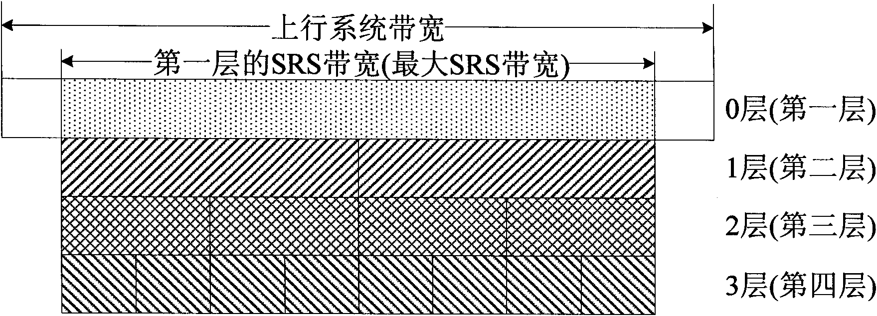
[0165] in no matter N b take what value, Both are 1, N bThe number of branches corresponding to the b layer when the SRS bandwidth tree structure is allocated, as shown in Table 1 to Table 4, n SRS is the sending counter of SRS, B SRS is the user-specific SRS bandwidth, b hop It is the user-specific frequency hopping bandwidth, and ∏ is the operation of multiplying multiple numbers.
[0166] When the terminal can support up to 4 transmitting antennas but only 2 of the 4 antennas are selected, 2 antennas are used as a group and divided into two groups, such as antenna 0 and antenna 2 as a group, antenna 1 and antenna 3 For a group, or any combination, select a group of antennas from the two groups to transmit the SRS, and the method described above can also be used.
[0167] Further, the base station configures the multi-antenna terminal to adopt a single-antenna transmission mode or a multi-antenna transmission mode through high-layer signaling or downlink control signaling.
Example Embodiment
[0168] Example two
[0169] When a terminal configured with multiple antennas has only one antenna to send SRS at the same time, that is, when the terminal is in single-antenna transmission mode:
[0170] When the antenna selection is disabled, the terminal sends SRS on a fixed antenna;
[0171] When antenna selection is enabled,
[0172] 1) If the terminal can support up to 4 transmitting antennas, the following methods are used for antenna selection and transmission:
[0173] When the frequency hopping of SRS in the frequency domain is not enabled, the antenna index a(n SRS ) is calculated as: a(n SRS ) = n SRS mod4;
[0174] When SRS frequency hopping in the frequency domain is enabled, the antenna index a(n SRS ) is calculated as:
[0175]
[0176]
[0177] in no matter N b take what value, Both are 1, N b The number of branches corresponding to the b layer when the SRS bandwidth tree structure is allocated, as shown in Table 1 to Table 4, n SRS is the sending counter of SRS, B SRS is the user-specific SRS bandwidth, b hop It is the user-specific frequency hopping bandwidth, and ∏ is the operation of multiplying multiple numbers.
[0178] Further, the base station configures the multi-antenna terminal to adopt a single-antenna transmission mode or a multi-antenna transmission mode through high-layer signaling or downlink control signaling.
Example Embodiment
[0179] Example three
[0180] Orthogonal resources are allocated to different antennas by code division multiplexing (CDM), time division multiplexing (TDM), or frequency division multiplexing (FDM), or any combination of the above, and each antenna transmits on the orthogonal resources Uplink SRS.
[0181] Further, the resource allocation mode is configured by the base station to the terminal through high-level signaling or downlink control signaling;
[0182] Further, before allocating orthogonal resources for different antennas, the base station (eNB) notifies the terminal equipment (UE) of resources for sending uplink SRS by each antenna through high-level signaling or downlink control signaling; or, the eNB transmits uplink SRS resources through high-level signaling or downlink control signaling Signaling notifies the UE of resources and resource allocation methods for some antennas to send uplink SRSs, and the UE determines resources for sending SRSs for each antenna according to the configured implicit mapping relationship.
[0183] Further, the allocating orthogonal resources for different antennas through CDM includes: allocating orthogonal code domain resources for sending uplink SRSs to different antennas through CDM;
[0184] The allocation of orthogonal resources for different antennas through TDM includes: allocating orthogonal time domain resources for sending uplink SRSs to different antennas through TDM;
[0185] The allocating orthogonal resources for different antennas through FDM includes: allocating orthogonal frequency domain resources for sending uplink SRSs to different antennas through FDM;
[0186] The allocation of orthogonal resources for different antennas through CDM combined with TDM includes: allocating orthogonal code domain resources for sending uplink SRSs to different antennas through CDM, and/or allocating resources for sending uplink SRSs for different antennas through TDM Orthogonal time domain resources;
[0187] The allocation of orthogonal resources for different antennas by means of TDM combined with FDM includes: allocating orthogonal time domain resources for sending uplink SRSs to different antennas by means of TDM, and/or allocating resources for sending uplink SRSs for different antennas by means of FDM Orthogonal frequency domain resources;
[0188] Further, the code domain resource is: root sequence and/or cyclic shift of the root sequence; the time domain resource is: subframe position or subframe offset; the frequency domain resource is: frequency band and/or frequency comb;
[0189] Further, for periodic SRS, use CDM combined with TDM to allocate orthogonal resources for different antennas, or use TDM combined with FDM to allocate orthogonal resources for different antennas;
[0190] Further, for aperiodic SRS, adopt CDM or FDM to allocate orthogonal resources for different antennas;
[0191] Further, when the terminal can support up to 4 transmitting antennas but only 2 of the 4 antennas are selected, 2 antennas are used as a group and divided into two groups, such as antenna 0 and antenna 2 as a group, and antenna 1 And antenna 3 as a group, or any combination, select a group of antennas to send SRS from the two groups, use the above-mentioned method of selecting 1 transmitting antenna from 2 transmitting antennas; use CDM or FDM to transmit SRS at the same time Two antennas allocate orthogonal resources.
[0192] Further, the base station configures the multi-antenna terminal to adopt a single-antenna transmission mode or a multi-antenna transmission mode through high-layer signaling or downlink control signaling.
[0193] Further, when the base station does not have high-level signaling or downlink control signaling to configure the SRS resource allocation mode of the terminal, the terminal can configure multi-antenna SRS resources through the following two methods:
[0194] Method 1: configure the SRS resource allocation mode according to the length of the UE-specific SRS period. When the configuration period is relatively long and is greater than a certain threshold value M, resources are configured in the manner of CDM or FDM; otherwise, resources are configured in the manner of TDM or TDM combined with CDM or TDM combined with FDM. Where M is an integer between 5 and 320 and a multiple of 5, and the unit is milliseconds (ms).
[0195] Method 2: configure the SRS resource allocation mode according to whether the SRS is hopping in the frequency domain. When frequency domain hopping is disabled (Hopping disabled), such as when b hop ≥B SRS When the TDM method is used; when the frequency domain frequency hopping is enabled (Hopping enabled), such as when b hop SRS , use CDM or FDM.
[0196] Further, when the resource allocation method used includes the CDM method, the CS interval of each antenna should be maximized, for example, the following formula is used to allocate CS resources:
[0197] no cs,i =(α·n cs,j +i·N/T x ) mod N
[0198] Where, i is the antenna port index, α=±1, n CS,j The cyclic shift used to send the uplink SRS for the known antenna port j, N is the total number of cyclic shifts, T x is the number of antennas transmitting SRS at the same time, i=0, 1,..., T x -1,j=0,1,...,T x -1
[0199] The present invention also provides a terminal, wherein: the terminal is used to acquire an antenna transmission mode, and transmit a measurement reference signal (SRS) according to the antenna transmission mode.
[0200] Wherein, the terminal is used for: when in the single-antenna transmission mode:
[0201] When the antenna selection is not enabled, the measurement reference signal is sent on a fixed antenna;
[0202] When antenna selection is enabled and the terminal supports 4 transmit antennas, when the antenna index is a(n SRS ) on the antenna that sends the nth SRS measurement reference signal, where the antenna index a(n SRS ) is determined as follows:
[0203] When SRS frequency hopping in the frequency domain is not enabled,
[0204] a(n SRS ) = n SRS mod4;
[0205] When SRS frequency hopping in the frequency domain is enabled,
[0206]
[0207]
[0208] in is 1, N b′ The number of branches corresponding to layer b' when assigning the SRS bandwidth tree structure, n SRS is the sending counter of SRS, B SRS is the user-specific SRS bandwidth, b hop It is the user-specific frequency hopping bandwidth, and ∏ is the operation of multiplying multiple numbers.
[0209] Wherein, the terminal is used: when it supports 2 transmitting antennas and is in a single-antenna transmitting mode, or supports 2 groups of transmitting antennas, each group of transmitting antennas includes at least 2 transmitting antennas, and one of the transmitting antennas needs to be selected When sending measurement reference signals:
[0210] at antenna index or group index a(n SRS ) on the antenna or group of antennas to transmit the nth SRS measurement reference signals, where the antenna index or group index a(n SRS ) is determined as follows:
[0211] When the frequency hopping of SRS in the frequency domain is not enabled, a(n SRS ) = n SRS mod2;
[0212] When SRS frequency hopping in the frequency domain is enabled,
[0213]
[0214] in is 1, N b′ The number of branches corresponding to layer b' when assigning the SRS bandwidth tree structure, n SRSis the sending counter of SRS, B SRS is the user-specific SRS bandwidth, b hop It is the user-specific frequency hopping bandwidth, and ∏ is the operation of multiplying multiple numbers.
[0215] Wherein, the terminal is configured to: when in the multi-antenna transmission mode, obtain the orthogonal resources allocated by the base station for transmitting the measurement reference signal on each antenna, and transmit the measurement reference signal on the orthogonal resources on each antenna Signal.
[0216] Wherein, the orthogonal resource is allocated by the base station to each of the resource allocation modes of code division multiplexing (CDM), time division multiplexing (TDM) and frequency division multiplexing (FDM). antenna.
[0217] Wherein, the allocation of orthogonal resources through CDM resource allocation includes allocation of orthogonal code domain resources through CDM; the allocation of orthogonal resources through TDM resource allocation includes allocation of orthogonal time domain resources through TDM; the allocation of orthogonal time domain resources through FDM The resource allocation method allocates orthogonal resources including allocating orthogonal frequency domain resources through FDM; the code domain resources are: the root sequence and/or the cyclic shift of the root sequence; the time domain resources are: subframe positions or subframes Offset; the frequency domain resource is: a frequency band and/or a frequency comb.
[0218] Wherein, the terminal is used to: directly obtain the orthogonal resource used for sending the measurement reference signal on each antenna from high-level signaling or downlink control signaling; Obtain the orthogonal resources used to send the measurement reference signal on some antennas in the signaling, and determine the orthogonal resources used to send the measurement reference signal on each antenna in combination with the resource allocation method and the configured implicit mapping relationship .
[0219] Wherein, the terminal is used to obtain the resource allocation method according to the following method:
[0220] Obtain the resource allocation mode from high-level signaling or downlink control signaling;
[0221] Or, determine the resource allocation mode according to a user terminal-specific measurement reference signal period;
[0222] Alternatively, the resource allocation manner is determined according to whether the measurement reference signal hops in the frequency domain.
[0223] Wherein, the terminal is used to obtain the resource allocation method according to the following method:
[0224] When the measurement reference signal period is greater than the threshold value M, use CDM or FDM resource allocation, otherwise use TDM, or TDM combined with CDM, or TDM combined with FDM resource allocation, the M is between 5 and 320 An integer that is a multiple of 5, and the unit is milliseconds.
[0225] Wherein, the terminal is used to obtain the resource allocation method according to the following method:
[0226] When the frequency domain hopping is disabled, the TDM resource allocation mode is used; when the frequency domain frequency hopping is enabled, the CDM or FDM resource allocation mode is used.
[0227] Wherein, the antenna transmission mode of the terminal refers to the antenna transmission mode of the physical uplink shared channel or the physical uplink control channel or the measurement reference signal, and the terminal is used to judge the antenna transmission mode through high-layer signaling or downlink control signaling as Single-antenna transmission mode or multi-antenna transmission mode.
[0228] The present invention also provides a base station, which is used for allocating orthogonal resources to the antennas, so that the antennas send measurement reference signals on the orthogonal resources.
[0229] Wherein, the base station is configured to: for the periodic measurement reference signal, allocate the orthogonal resources to the antennas in a CDM combined with TDM resource allocation manner.
[0230] Wherein, the base station is configured to: for the aperiodic measurement reference signal, allocate the orthogonal resources to the antennas in a CDM combined with FDM resource allocation manner.
[0231] Wherein, the base station is used for: when the terminal supports 2 groups of transmitting antennas, each group of transmitting antennas includes at least 2 transmitting antennas, and the terminal selects one group of transmitting antennas to transmit measurement reference signals, adopt CDM or FDM resource allocation The method allocates orthogonal resources for transmitting measurement reference signals to each antenna in the group of transmitting antennas.
[0232] Wherein, the base station is used for: when using the CDM resource allocation method, or combining the CDM resource allocation method and other resource allocation methods to allocate orthogonal resources for the antennas, the cyclic shift (CS) interval of each antenna should be maximized change.
[0233] Wherein, the base station is used for: allocating CS resources as follows:
[0234] no cs,i =(α·n cs,j +i·N/T x ) mod N
[0235] Where, i is the antenna port index, α=±1, n cs,j The cyclic shift used to transmit the measurement reference signal for the known antenna port j, N is the total number of cyclic shifts, T x is the number of antennas that transmit measurement reference signals at the same time, i=0, 1,..., T x -1,j=0,1,...,T x -1.
PUM


Description & Claims & Application Information
We can also present the details of the Description, Claims and Application information to help users get a comprehensive understanding of the technical details of the patent, such as background art, summary of invention, brief description of drawings, description of embodiments, and other original content. On the other hand, users can also determine the specific scope of protection of the technology through the list of claims; as well as understand the changes in the life cycle of the technology with the presentation of the patent timeline. Login to view more.