
Reduction gear

A reducer and input shaft technology, applied in mechanical equipment, gear transmission, belt/chain/gear, etc., can solve the problems of the durability of the reducer, miniaturization of the reducer, and obstacles to high output, and achieve weight reduction. , The effect of alleviating stress concentration and easy processing

Active Publication Date: 2013-02-13
SUMITOMO HEAVY IND LTD
View PDF3 Cites 0 Cited by
  • Summary
  • Abstract
  • Description
  • Claims
  • Application Information

AI Technical Summary

Problems solved by technology

In addition, this heat has a great influence on the durability of the reducer, and becomes an obstacle to downsizing and increasing the output of the reducer.

Method used


Image

  • Reduction gear
  • Reduction gear
  • Reduction gear

Examples


Embodiment Construction

[0029] Hereinafter, an example of an embodiment of the present invention will be described in detail with reference to the drawings.

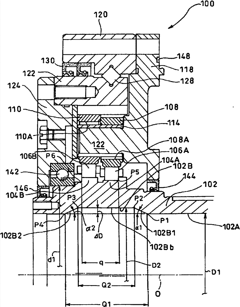
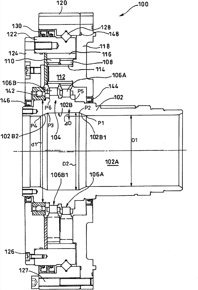
[0030] figure 2 It is a side sectional view of the speed reducer according to an example of the first embodiment of the present invention, figure 1 yes figure 2 An enlarged view of the main part.

[0031] The speed reducer 100 includes: an input shaft 102; first and second eccentric bodies 104A and 104B integrally provided on the input shaft 102; 2. External gears 108, 110; and an internal gear 122 internally meshing with the first and second external gears 108, 110. The input shaft 102 has a hollow portion 102A having an inner diameter D1, and recessed portions 102B are formed corresponding to axial positions where the first and second eccentric bodies 104A and 104B are formed. Describe in detail below.

[0032] The input shaft 102 is rotatably supported by a bearing 142 arranged in the vicinity of the second eccentric body 104B and a b...


PUM


Abstract

A reduction gear having an input shaft and an eccentric body mounted to the input shaft has a specially devised structure which allows efficient dissipation of heat produced by rotation of the input shaft. The reduction gear (100) has first and second eccentric bodies (104A, 104B) mounted to the input shaft (102) and takes out, as an output, relative rotation between an internally toothed gear (122) and first and second externally toothed gears (108, 110). The input shaft (102) has a hollow (102A). The first and second eccentric bodies (104A, 104B) are formed integrally with the input shaft (102). A recess (102B) is fully circumferentially formed in the input shaft (102) at an axial position at which the first and second eccentric bodies (104A, 104B) are formed. Cut ridgelines (102B1, 102B2) of the recess (102B) are tilted relative to a plane normal to the axis (O) of the input shaft (102).

Description

technical field [0001] This application claims priority based on Japanese Patent Application No. 2007-330743 filed on December 21, 2007 and Japanese Patent Application No. 2008-164763 filed on June 24, 2008. The entire contents of these applications are incorporated herein by reference. [0002] The present invention relates to a reduction gear having a heat radiation structure and a method for manufacturing an input shaft thereof. Background technique [0003] Conventionally, an input shaft, an eccentric body provided on the input shaft, an external gear provided outside the eccentric body, and an internal gear internally meshed with the external gear are known, and the relative rotation between the external gear and the internal gear is regarded as A reduction gear for outputting output (for example, refer to Japanese Patent Application Laid-Open No. 2001-187945). In such a speed reducer, when the input shaft rotates, the eccentric body provided on the input shaft rotate...

Claims


Application Information

Patent Timeline
Patent Type & Authority Patents(China)
IPC IPC(8): F16H1/32
CPCF16H1/32
Inventor 山本章田村光扩志津庆刚池上雅人
Owner SUMITOMO HEAVY IND LTD
Learn More