
battery cooling system

A cooling system and battery technology, applied in the direction of batteries, secondary batteries, battery pack components, etc., can solve the problems of insufficient and insufficient effect, and achieve the effect of effective heat release

Active Publication Date: 2018-03-27
DENSO CORP
View PDF6 Cites 0 Cited by
  • Summary
  • Abstract
  • Description
  • Claims
  • Application Information

AI Technical Summary

Problems solved by technology

[0006] That is, in Publication No. '605, there is only a small amount of air in contact with the case wall - the case wall serves as a heat release surface for air intake, air passing through the battery cell, and exhaust to the outside, Thus the heat released to the outside is insufficient
[0007] Therefore, regarding the point of efficiently releasing the heat generated by the battery to the outside of the case, a sufficient effect cannot be obtained in the conventional system, and there is room for improvement

Method used


Image

  • battery cooling system
  • battery cooling system
  • battery cooling system

Examples


no. 1 approach

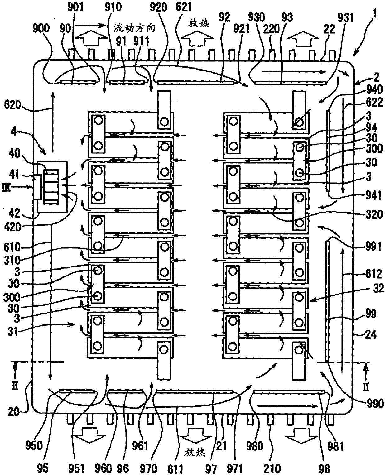
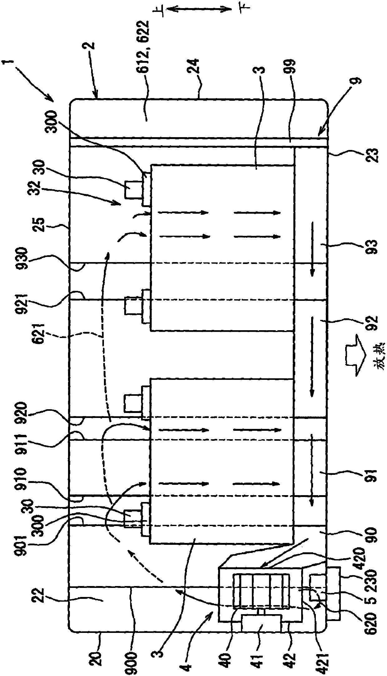
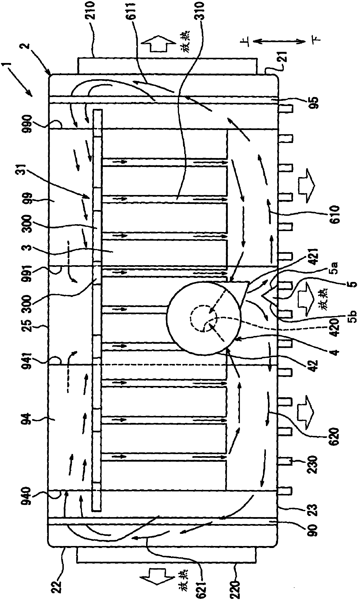
[0048] refer to Figure 1 to Figure 3 , the battery cooling system 1 related to the first embodiment of the present invention will be described below.

[0049] Figure 1 to Figure 3 is a schematic diagram showing the fluid flow for cooling the battery in the battery cooling system 1 and the composition of the interior of the housing 2 .

[0050] The battery cooling system 1 is used for a vehicle such as a hybrid car or an electric vehicle that uses an internal combustion engine and a motor as a driving source by combining an internal combustion engine and a motor driven by electric power charged in a battery, and an electric vehicle that uses, for example, A motor is used as a driving source.

[0051] The plurality of batteries included in the battery cooling system 1 may be, for example, nickel-metal hydride rechargeable batteries, lithium-ion rechargeable batteries, or organic compound batteries.

[0052] The battery cooling system 1 has a plurality of battery cells 3, a ...

no. 2 approach

[0280] Refer to the second embodiment Figure 4 and Figure 5 The passage forming member 109 is explained, which has a form different from that of the above-described embodiment.

[0281] exist Figure 4 and Figure 5In , components having the same composition as those of the first embodiment are given the same reference numerals, and have the same functions and effects.

[0282] In addition, the composition, function, and effect not particularly described in the second embodiment are the same as those of the above-mentioned embodiment.

[0283] Hereinafter, only differences from the above-described embodiment will be described.

[0284] The passage forming member 9 of the above-described embodiment may be replaced by a passage forming member 109 described below.

[0285] In a case forming a sealed space, the passage forming member 109 of the second embodiment is a component integrally formed with at least a single wall.

[0286] The passage forming member 109 is compose...

no. 3 approach

[0302] Refer to the third embodiment Figure 6 to Figure 8 The battery cooling system 101 will be described, which has a different form from the previous embodiments.

[0303] exist Figure 6 to Figure 8 In , components having the same composition as those of the first embodiment are given the same reference numerals, and have the same functions and effects.

[0304] In addition, the composition, function, and effect not particularly described in the third embodiment are the same as those of the foregoing embodiment.

[0305] Hereinafter, only points different from the foregoing embodiment will be described.

[0306] The passage forming member 109 of the second embodiment described above may be replaced by the passage forming member 9 of the third embodiment.

[0307] The battery cooling system 101 of the third embodiment also has fluid flow guiding units 7 , 8 .

[0308] The fluid flow guide unit 7, 8 is formed on one of the walls of the housing 2 forming the sealed space...


PUM


Abstract

The invention provides a battery cooling system (1), comprising: a casing (2) having walls surrounding an interior space in which a plurality of batteries (3) are accommodated; a blower (4) , the blower (4) is accommodated in the casing (2) and circulates fluid for cooling the plurality of battery cells (3) inside the casing (2); and a wall passage forming member (9). The wall passage forming member (9) forms a wall passage (611, 612, 622, 621). The wall passage forming member (9) has an inflow part and an outflow part through which the fluid from the blower (4) passes when flowing into the wall passage before contacting the battery (3), and the fluid from the inflow part entering the wall passage Passes through the outflow when flowing out of the wall passage.

Description

technical field [0001] The invention relates to a battery cooling system for cooling a battery accommodated in a casing. Background technique [0002] The system disclosed in Japanese Patent Application Laid-Open Publication No. 2013-86605 connects an intake duct and an exhaust duct to an encapsulation case housing a plurality of battery cells, and sends air supplied from a cooling fan into the case through the intake duct , and the air is exhausted to the outside through the exhaust duct after heat exchange with the battery cells. [0003] That is, the air exhausted to the outside after the heat exchange will not immediately return to the inside of the case, and new air for cooling the battery is always sent into the inside of the case. [0004] In the system of publication No. '605, the air supplied from the cooling fan flows toward the battery cells after passing through the inside of the intake duct. [0005] Then, the air immediately after passing through the battery ...

Claims


Application Information

Patent Timeline
Patent Type & Authority Patents(China)
IPC IPC(8): H01M10/613H01M10/6563H01M50/209H01M50/224H01M50/227H01M50/289
CPCH01M10/4207H01M2220/20H01M50/227H01M50/209H01M50/224H01M50/289H01M10/625H01M10/6563H01M10/613Y02E60/10H01M10/6565
Inventor 山本启善井上美光
Owner DENSO CORP
Learn More