Trolley for downhill zip line thrill ride

a zip line and thrill ride technology, applied in the direction of braking systems, rope railways, roads, etc., can solve the problems of high friction and related heat, trolley pulleys may fail prematurely, and the costa rican system is really quite primitive, so as to increase the force applied by the brake pad, reduce the risk of personal injury, and reduce the effect of friction

Active Publication Date: 2012-06-28
LERNER SHAWN GEOFFREY +1
View PDF1 Cites 13 Cited by
  • Summary
  • Abstract
  • Description
  • Claims
  • Application Information

AI Technical Summary

Benefits of technology

[0006]The zip line trolley of the present invention is designed for permanent long-term installations of inclined-cable thrill rides, where factors of reliability, safety, low-maintenance, and minimal manipulation by operating personnel are paramount for successful commercial exploitation with minimal personal liability risk. A rider is suspended from the trolley as he / she descends along an inclined cable. The trolley is equipped with a stainless steel main pulley which rides on an upper surface of the inclined cable. The trolley has a brake pad forward of the main pulley which rides against the underside of the inclined cable. Force applied by the brake pad against the cable is accomplished by suspending the rider on the trolley behind the main pulley. The distance behind the main pulley is determined by the angle of inclination of the suspended cable, the weight fo the rider, and the desired maximum speed to be attained during descent. The trolley is designed for use by successive riders without removing the trolley from the inclined cable. After use by each rider, the trolley is towed back to the high-elevation departure point for use by a successive rider. The trolley has a frame to which the brake pad, main pulley, and other components are attached. The frame is constructed principally from a pair of spaced-apart parallel side plates and an inner beam, which is partially sandwiched between the side plates, and extends to the rear edges thereof. The inner beam and side plates are bolted together to form a rigid structure. The inner beam not only acts as a spacer between the side plates, but also has a gallery of block-T-shaped cross-section that extends the length of the inner beam and is open at the bottom. A plurality of apertures equally over the length of the gallery extend transversely through an upper portion thereof. A T-shaped shackle having at least one transverse aperture, is slidably installed and subsequently trapped within the gallery by a cover plate installed at the rear of the inner beam. The at least one transverse aperture in the shackle aligns with each of the transverse apertures in the inner beam as the shackle is slid from one end of the gallery to the other, thereby enabling the shackle to be pinned at incremental distances within the gallery by inserting at least one pull pin through at the least one transverse aperture in the shackle and through an aligned transverse aperture in the inner beam. The end plate has a central aperture to which the retrieval line can be secured with, for example, a carabiner. A bumper, which is preferably made of stainless steel, is bolted between front portions of the side plates. The bumper not only functions as a rigidifying spacer at the front end of the trolley, it also provides protection to the side plates from mechanical damage and wear. In addition, the bumper is has an upwardly-angled lower-front edge which engages a ramp on a receiver at the end of each ride, thereby increasing the force applied by the brake pad against the lower surface of the suspended cable. Greater force equates to greater friction and a faster conversion of kinetic energy of the rider and trolley to heat. The brake pad, which is equipped with transverse grooves which wipe water from the suspended cable as the brake pad slides against the underside thereof, is pivotally mounted on a shoulder bolt that is transversely installed through both side plates. In addition, a pair of rotation-limiting bolts also pass through the brake pad. Pivotal mounting of the brake pad ensures continual maximum contact of brake pad material with the suspended cable. The main pulley is installed in upper middle portion of the frame. The main pulley rotates on a pair of sealed ball bearing races that are pressed on a keyed shaft which slides into opposed grooves machined into each of the side plates. A first auxiliary pulley positioned above the brake pad limits rotation of the trolley about the main pulley shaft as the brake pad is released from the suspended cable during each retrieval operation. A second auxiliary pulley positioned directly behind the main pulley serves as a fail safe device in the extremely remote possibility that the main pulley should suffer catastrophic failure. Each of the auxiliary pulleys is preferably made of high-density polyethylene, and rotates on a hollow cylindrical stainless steel bushing that is transversely bolted in place between both side plates. Each of the unkeyed bushings slides into opposing grooves machined into the side plates. The grooves for the keyed shaft of the main pulley and for the auxiliary pulley bushings are accessible from upper edges of the side plates. A stepped, cylindrical wear insert is pressed into a circular aperture from the inner surface of each side plate. Both cylindrical wear inserts are opposite one another and prevent wear to the precision-machined side plates in the event the trolley becomes misaligned with respect to the cable during descent or retrieval operations. A safety bolt, which passes transversely through both side plates at a location between the brake pad and the front edge of the inner beam provides an anchor for a carabiner which connects a safety strap to a T-hanger on which the rider is suspended.

Problems solved by technology

The Costa Rican system is really quite primitive, having a trolley with a single deep-groove nylon pulley riding on the suspended cable.
Riders who are particularly heavy may generate so much friction and related heat that the trolley pulley may fail prematurely.
Such a system is potentially dangerous, as the riders, themselves, must take responsibility for maintaining their descent speeds within a safe range, in order to avoid smashing into the lower cable support tower.
However, in a country such as the U.S., the slip and fall plaintiffs' bar would kill it almost immediately.
Although maximum speeds in excess of 90 m.p.h. are attainable on the system, the maximum speed experienced by paying riders is automatically limited by the equipment to no more than about 55 m.p.h.

Method used


Image

  • Trolley for downhill zip line thrill ride
  • Trolley for downhill zip line thrill ride
  • Trolley for downhill zip line thrill ride

Examples


Embodiment Construction

[0069]The downhill thrill ride zip line trolley will now be described in detail with reference to the attached drawing FIGS. 1 through 54. It should be understood that although the drawings are intended to be merely illustrative, a reasonable attempt has been made to provide drawings which are drawn close to scale. In addition, an effort has been made to ensure that all components shown on a single drawing sheet are drawn to the same scale. For any three-digit item number, the first digit indicates the drawing figure number where the designated item is most clearly seen for the first time. For any four-digit number, the first two digits indicate the drawing figure number where the designated item is most clearly seen for the first time.

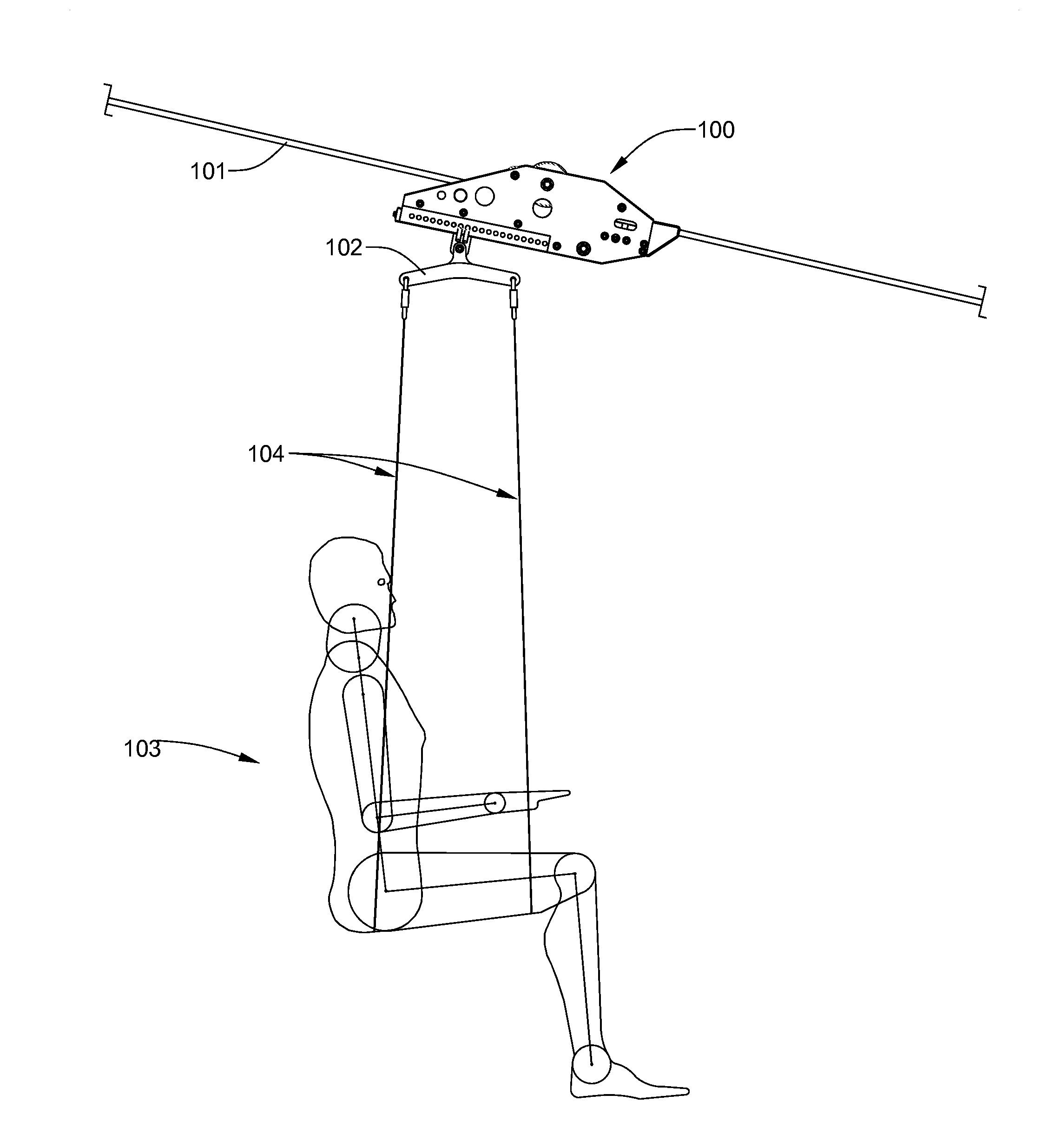
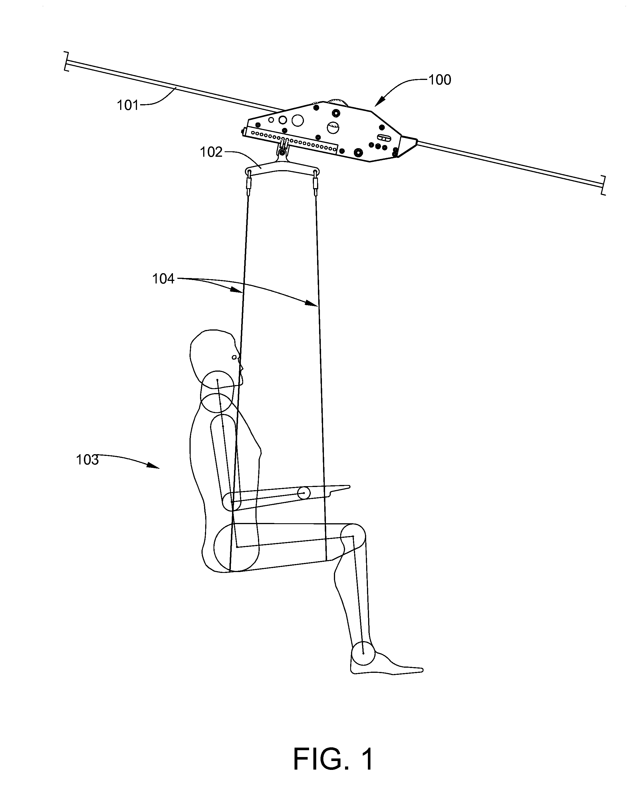
[0070]Referring now to FIG. 1, the zip line trolley 100 of the present invention is shown suspended from an inclined cable 101. The zip line trolley 100 is designed for permanent, long-term installations of inclined-cable thrill rides, where factors o...


PUM


Abstract

A zip line trolley includes a frame assembled from a pair of spaced-apart parallel side plates and an inner beam, which is partially sandwiched between the side plates. The inner beam has a gallery of block-T-shaped cross section which extends its length. A shackle, from which a rider is suspended, can be pinned anywhere within the gallery. A main pulley, which is installed in an upper middle portion of the frame, rotates on a pair of sealed ball bearing races that are pressed on a hollow keyed shaft which slides into opposed grooves machined into each of the side plates. The keyed shaft is bolted between the side plates with a shoulder bolt passing transversely through both side plates. A water-wiping brake pad is pivotally mounted within the frame in front of the main pulley. A bumper is bolted between front portions of the side plates.

Description

FIELD OF THE INVENTION[0001]This invention relates, generally, to suspended cable transport systems commonly known as zip lines and, more particularly, to trolleys for downhill zip line systems which are securely attached to the suspended cable and are designed to control maximum descent speed within a safe range.BACKGROUND OF THE INVENTION[0002]Transport systems involving a trolley slidable along a suspended length of cable have been known in the art for many years. Commonly known as zip lines, such systems are extensively used for rescue work on ski lift equipment. They are also available as backyard toys for children and adults. Spring Swings, Inc. of Riviera Beach, Fla., manufactures a Fun Ride Deluxe Zip Line kit which can be installed between two trees or other suitable cable supports. The kit includes enough stranded steel aircraft cable for a ride of about 21 meters (70 feet) in length, cable tensioning devices, and a “super tough” double-pulley plastic trolley which travels...

Claims


Application Information

Patent Timeline
Patent Type & Authority Applications(United States)
IPC IPC(8): A63G21/20B61H7/00B61H9/02B61B7/00
CPCA63G21/20B61H9/02B61B7/00B60T11/046
Inventor LERNER, SHAWN GEOFFREYRICHARDSON, MICHAEL TROY
Owner LERNER SHAWN GEOFFREY
Why Eureka
Try Eureka