
Deflaker plate and methods relating thereto

一种高频疏解机、高频疏解的技术,应用在减少纤维材料中絮片的系统领域,能够解决高制造成本等问题

Inactive Publication Date: 2010-10-27
ANDRITZ AG
View PDF7 Cites 18 Cited by
  • Summary
  • Abstract
  • Description
  • Claims
  • Application Information

AI Technical Summary

Problems solved by technology

But machining the disc involves higher manufacturing costs and limits the ability to special designs of the opposing surfaces of the teeth
[0008] That is, precise machining inherently limits the design of high-frequency deflaker discs
For example, a machined deflaker disc may only have teeth in the shape of an annular ring, since the lathe may only cut concentric circles in the disc

Method used


Image

  • Deflaker plate and methods relating thereto
  • Deflaker plate and methods relating thereto
  • Deflaker plate and methods relating thereto

Examples


Embodiment Construction

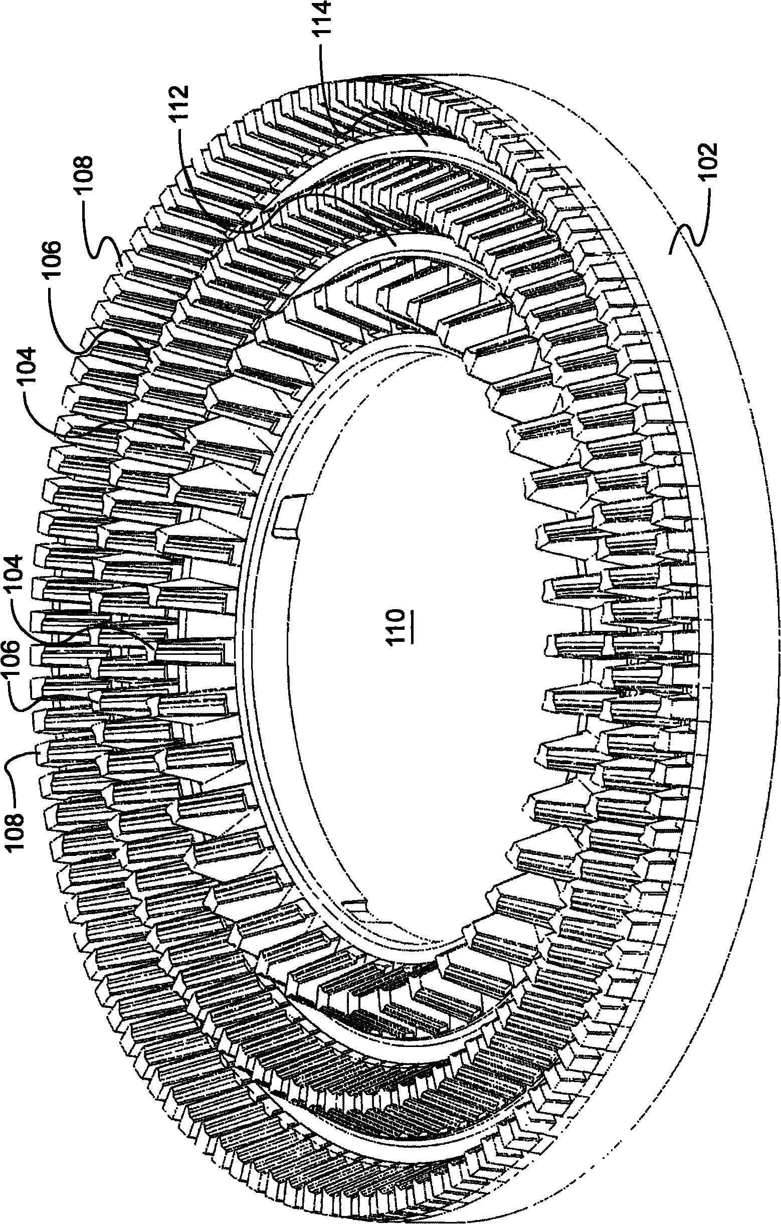
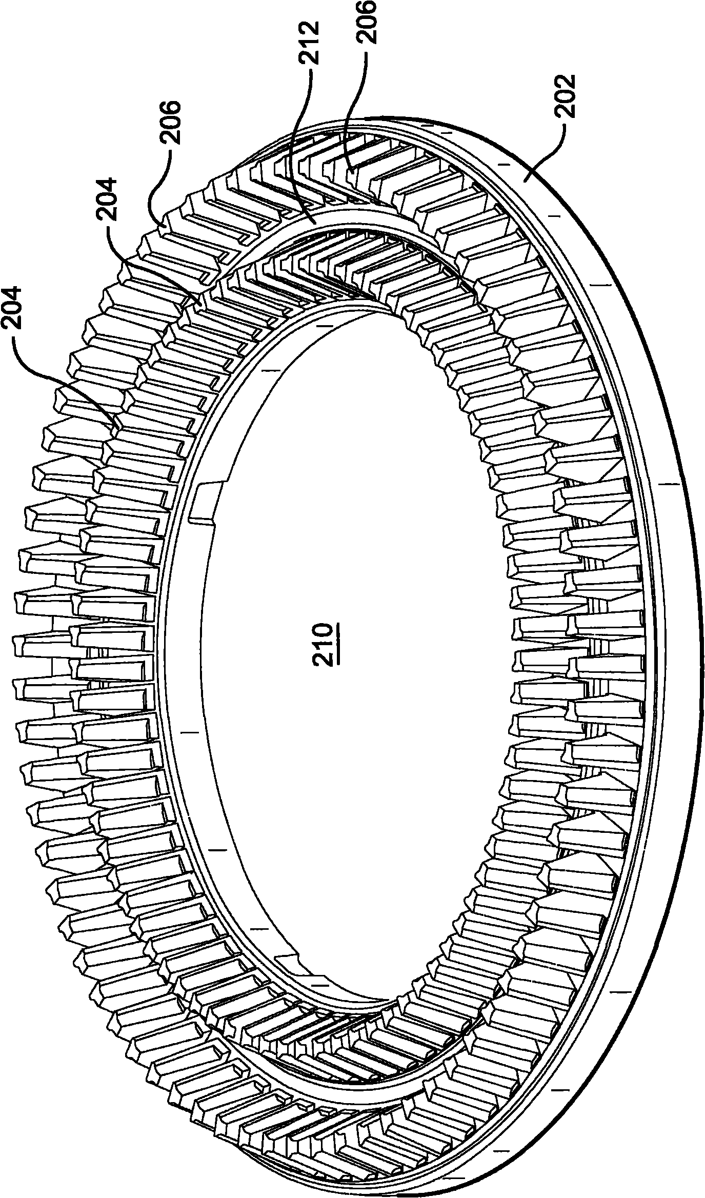
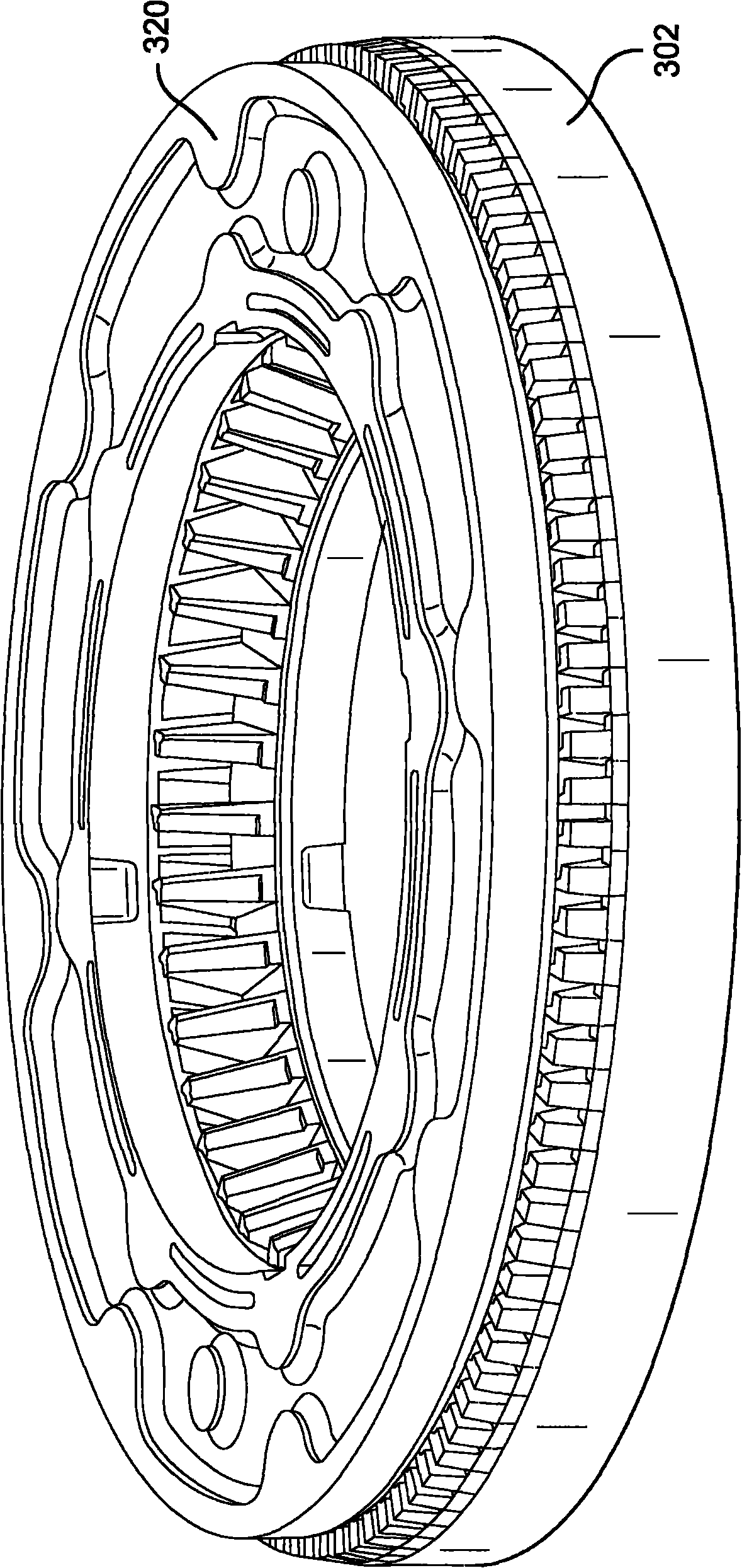
[0024] In one aspect, the invention relates to deflaker discs in which the surfaces of the teeth are not parallel (and perpendicular) to the axis of rotation of the disc. For example, the deflaker discs may have not substantially cubic teeth, but substantially conical or substantially triangular teeth. That is, the teeth may have front and rear surfaces, each of which is substantially triangular or trapezoidal in shape. These shapes, within the scope of certain aspects of the invention, can affect the magnitude and direction of hydraulic shock forces during rotor and stator tooth sweeping.

[0025] In some embodiments, the teeth may form one, two, three or more (eg five or ten) annular rings around each of the rotor and stator disks. Typically, the slurry flows from the center to the outer circumference of the disks (which preferably may rotate in opposite directions relative to each other, and / or in some embodiments at different frequencies or speeds), typically following a ...


PUM


Abstract

A deflaker plate for use in a deflaker for reducing fibrous flakes in a slurry of fibers. The deflaker plate may include at least one annular ring consisting of multiple teeth, in which at least one tooth has a leading face, a trailing face, and an impact-generating side-face. The impact-generating side-face may be adapted to generate an impact force during operation, such that the force corresponds to a first vector radially pushing the slurry towards a center of the deflaker and a second vector tangentially pushing the slurry towards the leading face.

Description

[0001] This application claims the benefit of priority to US Application No. 61 / 172,092, filed April 23, 2009, the contents of which are incorporated herein by reference. technical field [0002] The present invention generally relates to systems and methods for reducing flakes in fibrous materials. For example, the invention may have particular applicability in disintegrating fiber bundles and fibers for recycling in kraft or mechanical pulps and reducing flakes in broke handling systems. Background technique [0003] Converting fibrous material (eg lignocellulosic material) or paper (eg broke) into individualized fibers generally involves breaking down the fiber mat into fibers under the action of shear forces in a suspension environment. This can be done eg between two discs in a mechanical refiner. Repeated application of shear forces in the presence of water causes the fiber mat to dissolve the fiber compound into smaller and smaller pieces until it breaks down to the ...

Claims


Application Information

Patent Timeline
Patent Type & Authority Applications(China)
IPC IPC(8): D21B1/32
CPCD21D1/008D21D1/30
Inventor 彼得·安泰施泰纳
Owner ANDRITZ AG
Learn More