Pushing and drawing force testing machine

A push-pull force tester and pull test technology, which is applied in the direction of impact test, machine/structural component test, static/dynamic balance test, etc. It can solve the problems of difficult test process and poor repeatability of control test results, and achieve thrust and The pulling force is controllable, the operation is convenient, and the effect of improving accuracy

Inactive Publication Date: 2013-11-06
HONG FU JIN PRECISION IND (SHENZHEN) CO LTD +1
View PDF4 Cites 0 Cited by
  • Summary
  • Abstract
  • Description
  • Claims
  • Application Information

AI Technical Summary

Problems solved by technology

The test process is not easy to control and the repeatability of the test results is poor

Method used


Image

  • Pushing and drawing force testing machine
  • Pushing and drawing force testing machine
  • Pushing and drawing force testing machine

Examples


Embodiment Construction

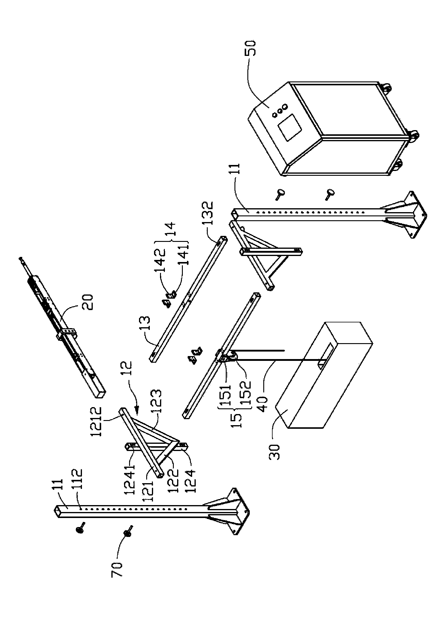
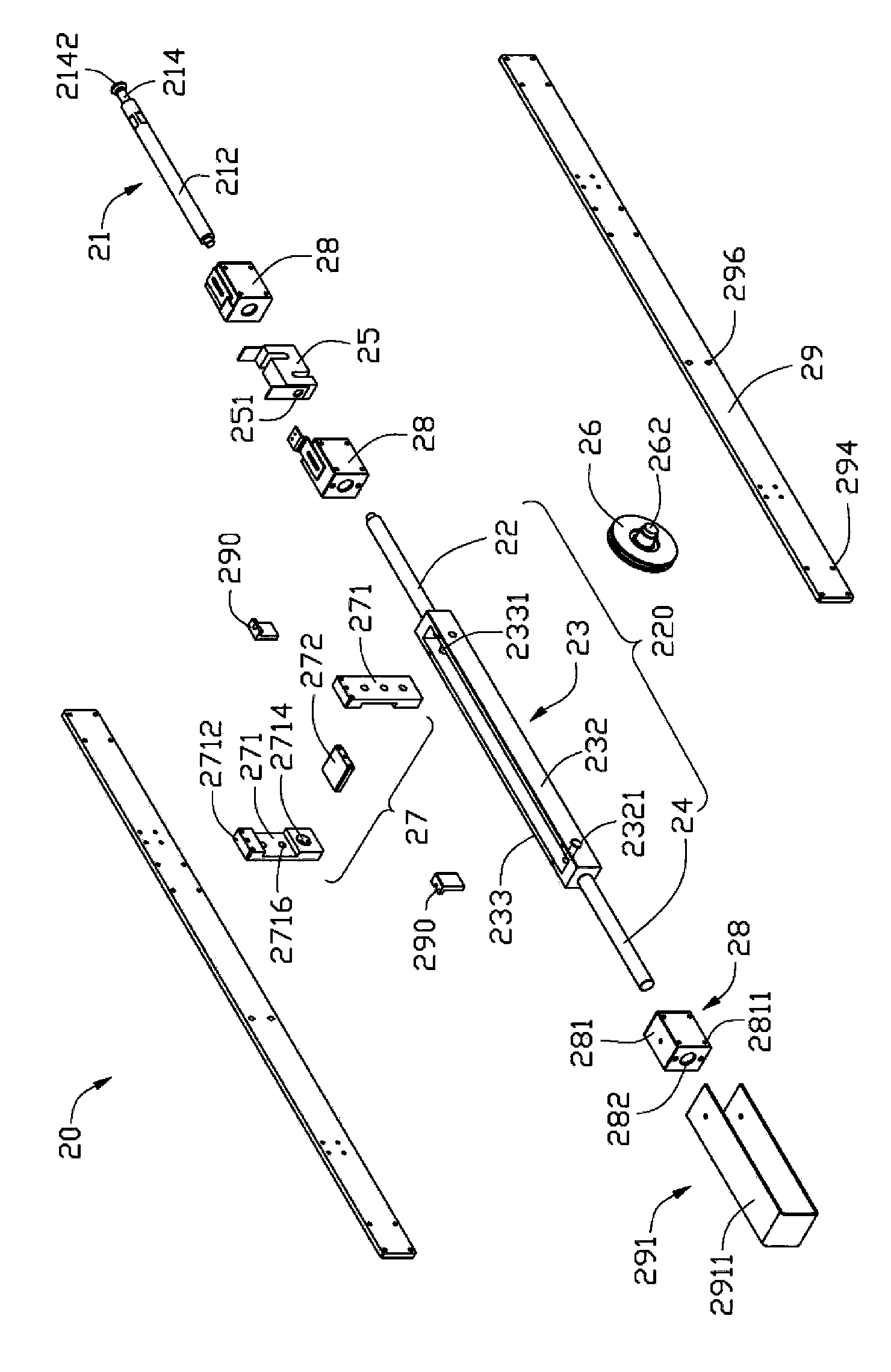
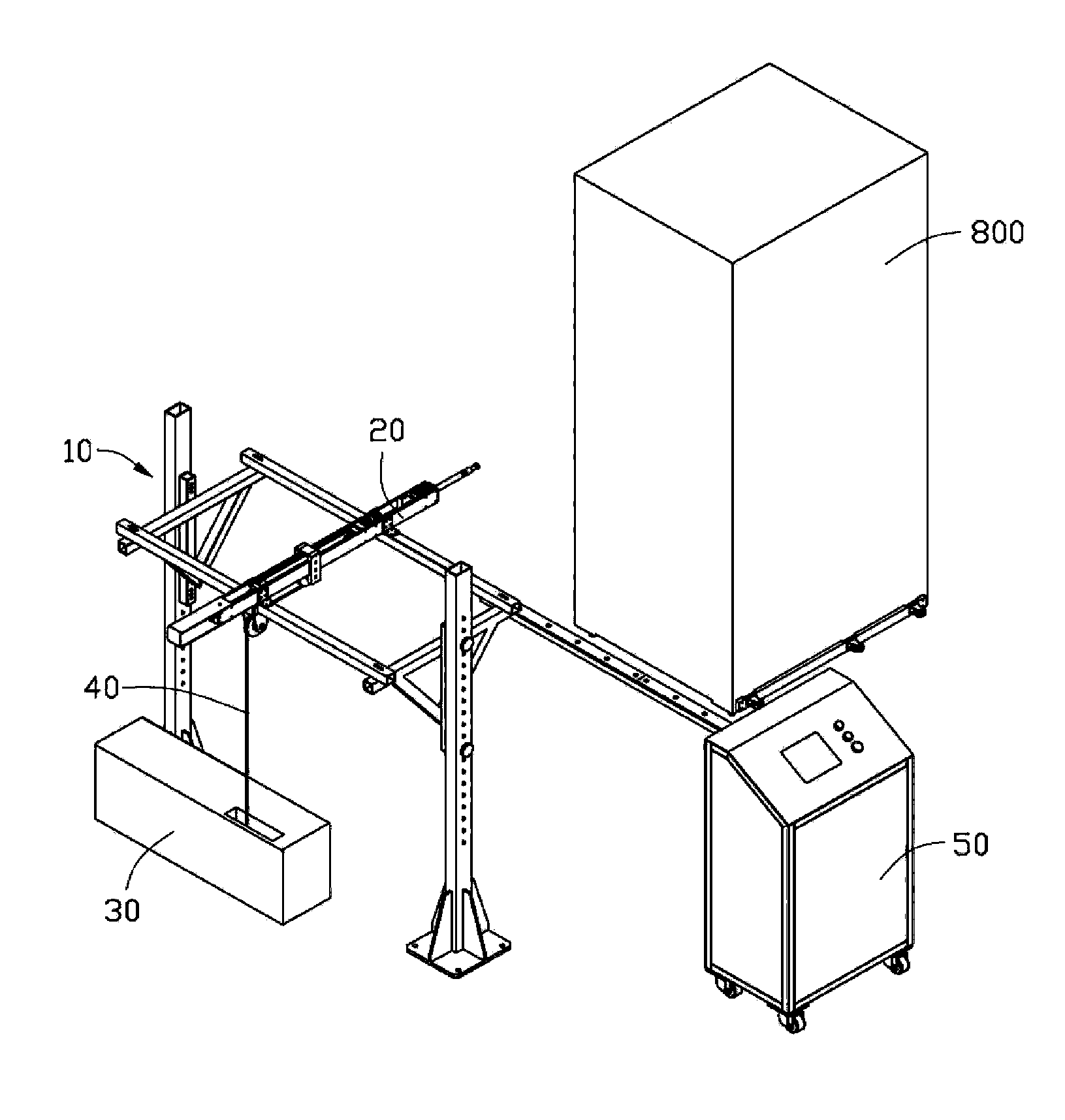
[0013] see Figures 1 to 3 , the push-pull force testing machine of the present invention is used to perform a push-pull force test on an electronic device 800 . The push-pull force testing machine includes a support device 10 , a push-pull force conversion mechanism 20 , a force applying device 30 , a rope 40 and a controller 50 . In this embodiment, the electronic device 800 is a server.

[0014] The supporting device 10 includes a pair of uprights 11 , a pair of supporting parts 12 , a pair of supporting rods 13 , two pairs of fixing parts 14 and a hanging part 15 . Two opposite sides of each column 11 are respectively provided with a plurality of fixing holes 112 along its longitudinal direction. Each bearing member 12 is triangular in shape and includes a first rod 121 , a second rod 122 and a third rod 123 connected end to end. A mounting portion 124 is further defined on a side of the supporting member 12 . The mounting portion 124 defines a plurality of threaded ho...


PUM


Abstract

The invention relates to a pushing and drawing force testing machine which is used for testing pushing force or drawing force for electronic equipment. The pushing and drawing force testing machine comprises a supporting device, a pushing and drawing force switching mechanism, a force application device and a rope, wherein the pushing and drawing force switching mechanism is fixed on the supporting device; the force application device is used for controlling the magnitude of output acting force; the rope is connected with the force application device and the pushing and drawing force switching mechanism; the pushing and drawing force switching mechanism comprises an actuating rod and a connecting component, wherein the actuating rod is butted with the electronic equipment or is connected with the electronic equipment through a connecting piece, and the connecting component is connected with the actuating rod and is provided with a first clamping column; and the force application device draws the rope to enable the actuating rod of the pushing and drawing force switching mechanism to push or draw the electronic equipment in a sliding way. The pushing and drawing force testing machine has the advantages of convenient operation and high reliability of test results.

Description

technical field [0001] The invention relates to a force testing device, in particular to a push-pull force testing machine. Background technique [0002] Large electronic equipment such as servers may be overturned or deformed due to external forces during use, thereby damaging the electronic equipment, and even causing personal injury due to the overturning of the electronic equipment. Therefore, large electronic equipment needs to be able to withstand certain external forces without overturning or deformation. [0003] In order to test the anti-overturning performance or anti-deformation ability of large electronic equipment, it is necessary to simulate the force condition of large electronic equipment during use. The existing method is to use a tester to apply a certain pushing or pulling force to the electronic device to be tested. The position and size of the force application are controlled by the experience of the tester. The test process is not easy to control and...

Claims


Application Information

Patent Timeline
Patent Type & Authority Patents(China)
IPC IPC(8): G01M1/00G01M7/08
Inventor 黄登聪余国俊胡永兵颜章胜龙丰
Owner HONG FU JIN PRECISION IND (SHENZHEN) CO LTD
Why Eureka
Try Eureka