Magnetic drive unit and a drive actuating mechanism with same

A magnetic drive and actuator technology, applied in the direction of electromagnets, electrical components, three-dimensional systems, etc., can solve the problems of drive execution efficiency, poor response sensitivity, low mechanism drive efficiency, and difficult micro-miniature structures, etc., to achieve drive High efficiency, simple structure, and large driving force

Active Publication Date: 2012-01-25
杨锦堂 +1
View PDF1 Cites 0 Cited by
  • Summary
  • Abstract
  • Description
  • Claims
  • Application Information

AI Technical Summary

Problems solved by technology

Such a set of mechanisms, due to too many components, the drive efficiency of the entire mechanism is not high, and because the mechanism must be equipped with a motor as a power source, and requires transmission mechanisms such as gears, bearings, clutches, etc., it is difficult to make such a mechanism small structure, the driver execution efficiency and response sensitivity will be poor, and it is not suitable for cluster and array driver execution applications

Method used


Image

  • Magnetic drive unit and a drive actuating mechanism with same
  • Magnetic drive unit and a drive actuating mechanism with same
  • Magnetic drive unit and a drive actuating mechanism with same

Examples


Embodiment 1

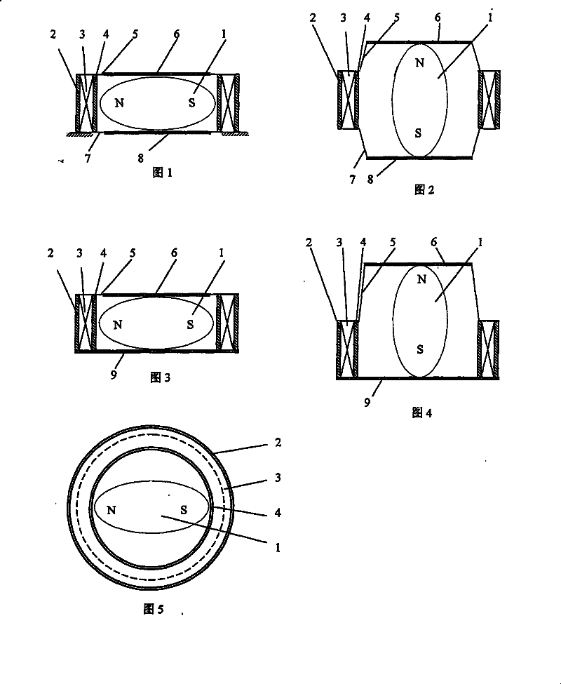
[0039] Such as figure 1 , figure 2 As shown, the magnetic drive unit includes a direction-shaped permanent magnet 1, an outer frame 2, an electromagnetic coil 3, an inner frame 4, an upper elastic membrane body 5, an upper rigid module 6, a lower elastic membrane body 7 and a lower rigid module 8; The frame 2 and the outer frame 4 are fixed and are cylindrical; the electromagnetic coil 3 is placed inside the outer frame 2 and wound outside the inner frame 4, and the permanent magnet 1 is freely placed on the upper surface covered by the inner frame 4 and the upper and lower end surfaces. In the cavity formed by the elastic membrane body 5 and the lower elastic membrane body 7; in addition, the upper rigid module 6 and the lower rigid module 8 are bonded to the upper elastic membrane body 5 and the lower elastic membrane body 7 respectively.

[0040] Wherein, the permanent magnet 1 is a permanent magnet ellipsoid particle with the longest length in the N-S direction of the ma...

Embodiment 2

[0043] Such as image 3 , Figure 4 As shown, the upper side of the inner frame 4 is provided with an upper elastic membrane body 5, and the lower side is fixed with a rigid baffle 9, and the others are the same as in Embodiment 1. During the working process of electromagnetic excitation, due to the support of the rigid baffle 9, the permanent magnet 1 has an overall upward lifting action process while rotating, and all the deformation of the permanent magnet 1 in the direction of the electromagnetic field is transferred to the upper part. The elastic membrane 5 and the upper rigid module 6 make the magnetic drive unit only exhibit one-way or one-sided expansion and contraction action.

Embodiment 3

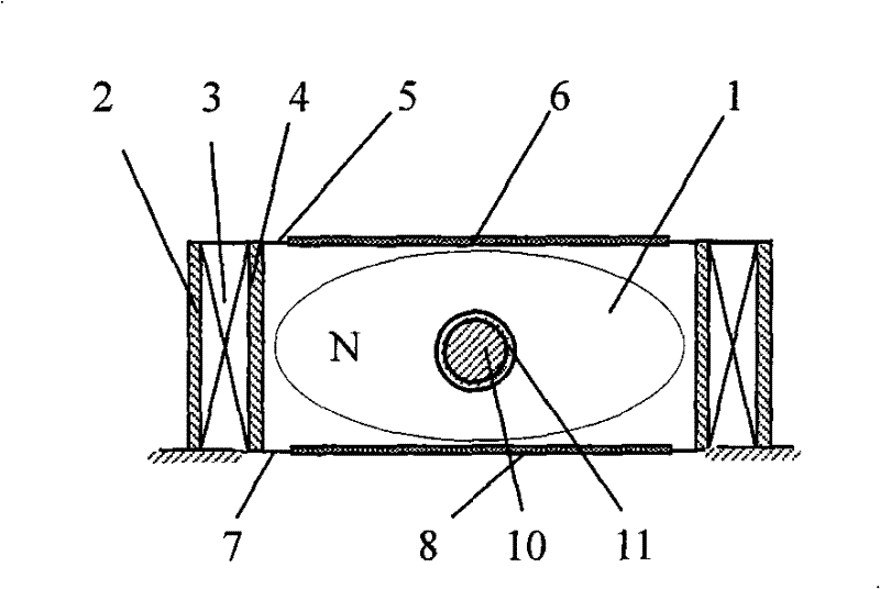
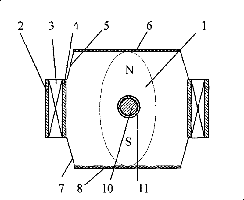
[0045] Such as Figure 6 , Figure 7 As shown, it includes a direction-shaped permanent magnet 1, an outer frame 2, an electromagnetic coil 3, an inner frame 4, an upper elastic membrane body 5, an upper rigid module 6, a lower elastic membrane body 7 and a lower rigid module 8; the inner and outer frames 2, 4 Fixed, the electromagnetic coil 3 is placed inside the outer frame 2 and wound outside the inner frame 4, the center of the permanent magnet 1 is drilled to assemble a bearing 11, the middle of the bearing 11 penetrates a rotating support rod 10, and the two ends of the rotating support rod 10 Placed in a chute 12 fixed on the inner frame 4. In this case, the permanent magnet 1 and the rotating support rod 10 are placed in the cavity formed by the upper elastic membrane body 5 and the lower elastic membrane body 7 covered by the inner frame 4 and the upper and lower end faces; in addition, the upper elastic membrane body 5. The upper module body sheet 6 and the lower m...


PUM


Abstract

The invention relates to a magnetic drive deformation device, particularly to a mechanism for three-dimensional dynamic or static display of two-dimensional information by using a magnetic drive deformation device. A magnetic drive unit provided by the invention is characterized by comprising an electromagnetic coil, an outer frame and an inner frame, wherein the electromagnetic coil is arranged in the outside frame and wound on the outer side of the inner frame; the upper side and the lower side of the inner frame are provided with an elastic membrane; a rigid module is attached to the elastic membrane; and permanent magnets in different directions are arranged in the cavity formed by the inner frame and the elastic membrane. The upper or lower side of the inner frame can be provided with an elastic membrane, and the other side can be fixed with a rigid baffle. The mechanism and an array thereof can be used for three-dimensional display of computer-digitized graphical information, signs and the like, and can be also used in the fields of motion control, drive actuation, remote transmission of movements and tactile sense, information transmission and the like.

Description

technical field [0001] The invention relates to a magnetically driven deformation device, in particular to a dynamic or static display mechanism for three-dimensional display of planar information through the magnetically driven deformation device. Background technique [0002] In recent years, computer graphics display technology has developed very well. Through computer graphics display technology, people can see various flat or three-dimensional graphics, dynamic and static video images, etc. on computer monitors, providing us with a rich and colorful digital information world. However, this computer digitized graphic information is essentially a virtual information, which can only be watched but not touched. If there is a technology that can present this kind of computer digitized graphics and symbols in the real physical world, and realize the physical and three-dimensional presentation of flat virtual digital information, then this technology will break through the bo...

Claims


Application Information

Patent Timeline
Patent Type & Authority Patents(China)
IPC IPC(8): H01F7/06H04N13/00H04N13/04
Inventor 杨锦堂李健
Owner 杨锦堂
Why Eureka
Try Eureka