Dual clutch transmission

A dual-clutch and transmission technology, which is applied in the direction of vehicle gearboxes, gear transmissions, transmission components, etc., can solve the problems of small axial structural dimensions and achieve the effect of saving axial structural space

Inactive Publication Date: 2010-11-03
GETRAG FORD TRANSMISSIONS GMBH
View PDF5 Cites 28 Cited by
  • Summary
  • Abstract
  • Description
  • Claims
  • Application Information

AI Technical Summary

Problems solved by technology

[0004] Although small axial dimensions can be achieved with the dual clutch transmission described in WO

Method used


Image

  • Dual clutch transmission
  • Dual clutch transmission
  • Dual clutch transmission

Examples


Embodiment Construction

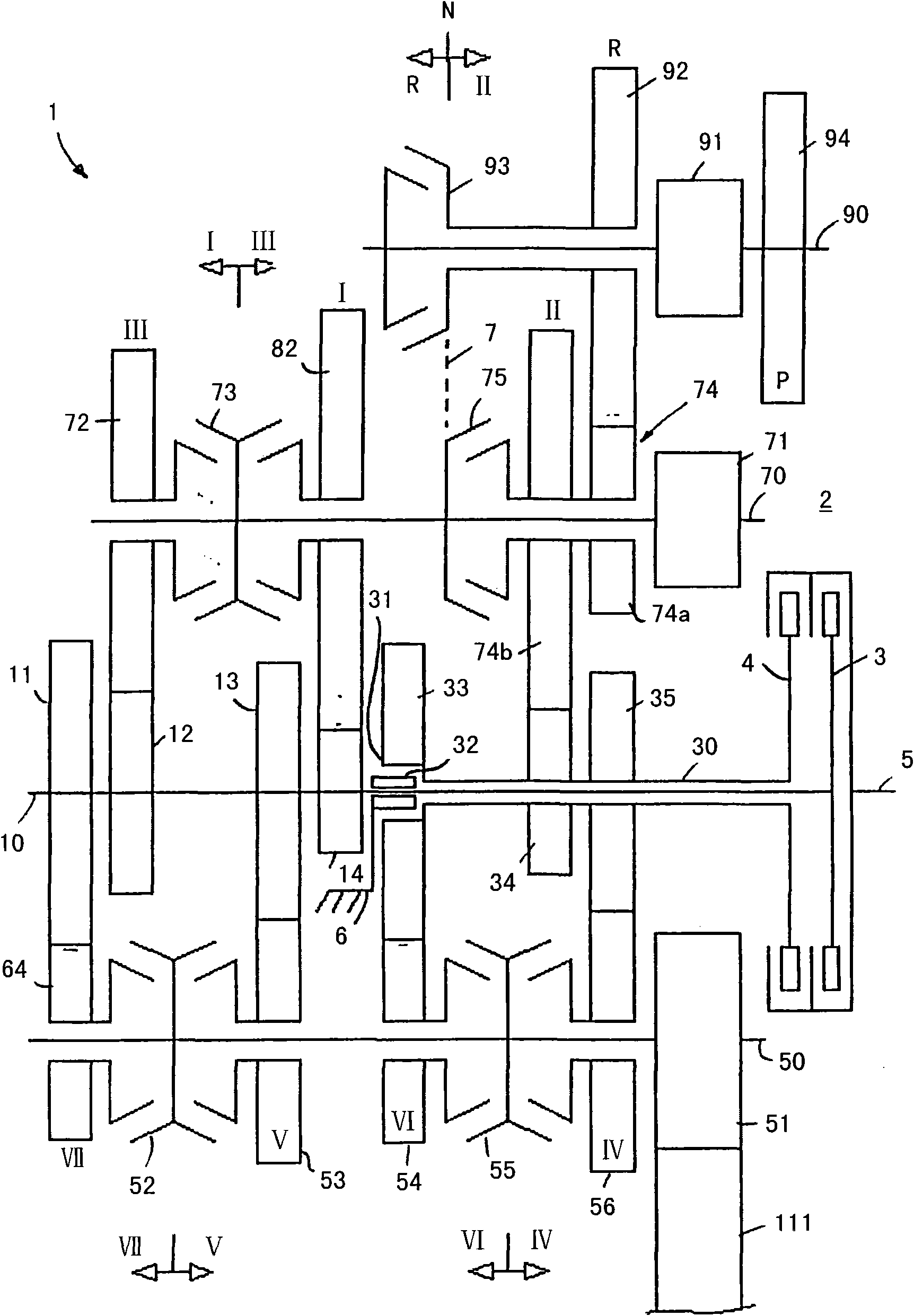
[0028] attached figure 1 Shown is a schematic view of the structure of the first embodiment of the dual-clutch transmission of the present invention, and the dual-clutch transmission is denoted by reference numeral 1 as a whole. The dual clutch transmission 1 has a first input shaft 10 and a second input shaft 30 arranged coaxially with one another. The second input shaft 30 is designed as a hollow shaft, the first input shaft 10 as a mandrel. Both the first clutch 3 and the second clutch 4 are arranged on the input side 2 of the dual clutch transmission 1 . The first input shaft 10 can be connected by means of the first clutch 3 to the crankshaft 5 of the engine, not shown in the figure. The second input shaft 30 can be connected to the crankshaft 5 by means of the second clutch 4 .

[0029] The first drive shaft 50 , the second drive shaft 70 and the third drive shaft 90 are all parallel to the coaxially arranged input shafts 10 , 30 . in the attached figure 1 In the di...


PUM


Abstract

The invention relates to a dual clutch transmission having a first input shaft (10) and a second input shaft (30), comprising a first drive shaft (50), a second drive shaft (70) and a third drive shaft (90), an output shaft (110) connected with the drive shafts (50,70,90) without relative rotating, a plurality of gears, wherein each gear corresponds with the gear connection comprising an idler gear and a fixed gear. An operated multi-level gear (74) comprising a first gear (74a) and a second gear (74b) is mounted on the second drive shaft (70) and the idler gear (92) of the reverse gear on the third drive shaft (90) is engaged with the first gear (74a) of the multi-level gear (74) and the fixed gear (34) of a second advancing gear (II) on the input shaft (30) is engaged with the second gear (74b) of the multi-level gear (74). The multi-level gear (74) is operated by a gear shift clutch (75) on the second drive shaft (70) and the gear shift clutch is used as the single-function gear shift clutch and the multi-level gear (74) is connected with the second drive shaft (70) without relative rotating.

Description

technical field [0001] The invention relates to a multi-speed dual-clutch transmission, which includes a first input shaft and a second input shaft and first, second and third drive shafts. Background technique [0002] WO 2006 / 128626 discloses such a dual clutch transmission in which three drive shafts are non-rotatably connected to an output in the form of a differential. A gear connection with an idler gear and a fixed gear is assigned to each gear position, wherein the idler gear of the respective gear connection can be non-rotatably connected via a shift clutch to the shaft supporting the idler gear. If a non-rotatable connection between the idler gear and the shaft has already been established via the gearshift clutch, the corresponding gear is engaged, so that a torque flow is established between one of the input shafts and the output. [0003] WO 2006 / 128626 discloses a dual clutch transmission with a multi-stage gear having a first gear and a second gear. The mult...

Claims


Application Information

Patent Timeline
IPC IPC(8): F16H3/093
CPCF16H2003/0931F16H3/006F16H2200/0056Y10T74/19228Y10T74/19233
Inventor H·恩斯特伦A·黑格拉特
Owner GETRAG FORD TRANSMISSIONS GMBH
Why Eureka
Try Eureka