
Clutch system with bearing in actuating device and drive unit

A technology for operating equipment and driving units, which is applied in the field of clutch systems, can solve problems such as expensive installation, and achieve the effect of compact, compact and stable support of the clutch system

Active Publication Date: 2019-07-30
SCHAEFFLER TECH AG & CO KG
View PDF14 Cites 0 Cited by
  • Summary
  • Abstract
  • Description
  • Claims
  • Application Information

AI Technical Summary

Problems solved by technology

[0003] It has proven to be a disadvantage of the known clutch systems that such clutch systems are generally of relatively large construction and can be complex to install

Method used


Image

  • Clutch system with bearing in actuating device and drive unit
  • Clutch system with bearing in actuating device and drive unit
  • Clutch system with bearing in actuating device and drive unit

Examples


Embodiment Construction

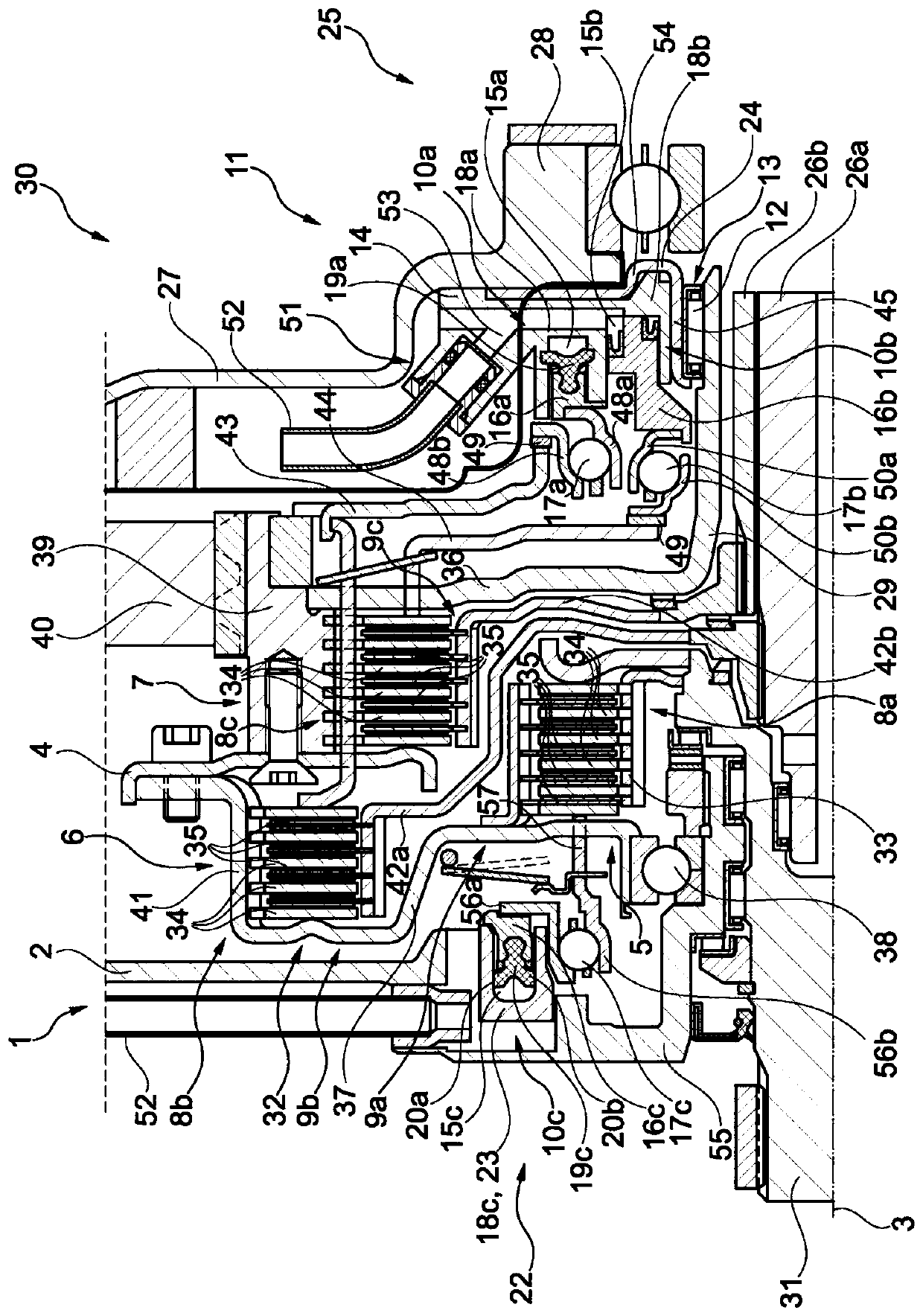
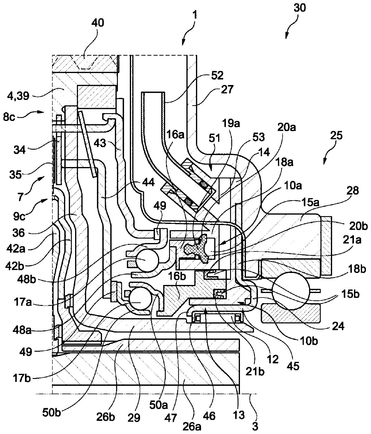
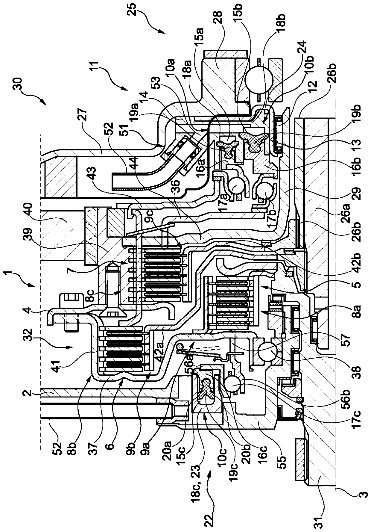
[0049] The first embodiment of the clutch system 1 according to the invention combines figure 1 Can be seen well. The clutch system 1 has been used in the drive unit 30 in this figure. The drive unit 30 forms a unit composed of the clutch system 1 and the transmission device 25 . With regard to the transmission device 25 , only the transmission housing 27 and the two transmission input shafts 26 a , 26 b rotatably accommodated in the transmission housing 27 are shown for the sake of clarity. During operation, drive unit 30 is typically a component of a hybrid drive train of a (hybrid) motor vehicle. As explained in detail below, the clutch system 1 is implemented as a hybrid module.

[0050] The clutch system 1 has a total of three clutches 5 , 6 , 7 . The clutch system 1 is therefore also referred to as a triple clutch. The first clutch 5 is arranged on the input side of the clutch system 1 in the form of a separating clutch. The input of the clutch system 1 is the regi...


PUM


Abstract

The invention relates to a clutch system (1) for a drive train of a motor vehicle, comprising: a housing (2); a carrier (4) which is mounted so as to be rotatable about an axis of rotation (3) relative to the housing (2); an electric machine, the rotor of which is rotationally coupled to the carrier (4); a plurality of clutches (5, 6, 7), wherein each clutch (5, 6, 7) is accommodated in a rotationally fixed manner on the carrier (4) by means of a clutch component (8 b, 8 c, 9 a); and an actuating device (11) having two auxiliary cylinders (10 a, 10 b), wherein each auxiliary cylinder (10 a, 10b) acts on the clutch (5, 6, 7) in an actuating manner, wherein the carrier (4) is supported via a support bearing (12) on the radially inner side (13) of an actuator housing (14) of the actuating device (11). The invention further relates to a drive unit (30) having the clutch system (1).

Description

technical field [0001] The present invention relates to a clutch system (also called a hybrid module) for a power train of a motor vehicle, such as a car, a truck, a bus or other trucks, which has: a housing; a carrier supported rotatably about an axis of rotation by the housing; an electric motor rotationally coupled to the carrier by means of its rotor; a plurality of clutches, each of which is held on the carrier in a rotationally fixed manner by means of a clutch component; and An actuating device with two secondary cylinders, each of which acts actuatingly on one of the clutches / clutches. Furthermore, the invention relates to a drive unit for a drive train of a motor vehicle, which has such a clutch system. Background technique [0002] Such clutch systems are well known in the prior art. An electric machine for a hybrid drive system of a motor vehicle is known, for example, from DE 10 2013 006 857 A1. Furthermore, WO 2017 / 186 227 A1 discloses a hybrid module and a d...

Claims


Application Information

Patent Timeline
Patent Type & Authority Applications(China)
IPC IPC(8): F16D25/10F16D25/08F16D25/12
CPCF16D25/10F16D25/082F16D25/12Y02T10/62
Inventor 西蒙·奥特曼菲利普·瓦格纳多丽丝·马里亚·罗伊特奥雷利昂·高尔斯
Owner SCHAEFFLER TECH AG & CO KG
Learn More