Storage battery grid plate

A battery and grid technology, applied in the direction of electrode carrier/current collector, can solve the problems of large force and easy fracture of transverse bars, and achieve the effect of not easy to fracture, increase conductive cross-sectional area, and improve transmission performance

Inactive Publication Date: 2010-11-03
长兴诺力电源有限公司
View PDF4 Cites 1 Cited by
  • Summary
  • Abstract
  • Description
  • Claims
  • Application Information

AI Technical Summary

Problems solved by technology

[0002] Existing battery grids, such as the "high-strength lead-acid battery grid" disclosed in the Chinese patent No. 90215614.4, are distributed on the grid frame Grid ribs are provided to make the grid into a grid-like grid, so that the nodes of the grid, that is, the intersections of the grid ribs, contain nodes in the shape of "m" or "X". The grid of this structure Although the transmission performance of the grid plate is effectively improved, because many oblique ribs are intersected at one point of the horizontal rib, the force on this point of the horizontal rib is relatively large, especially the transverse rib in the middle of the grid plate is the most stressed and easy to break

Method used


Image

  • Storage battery grid plate
  • Storage battery grid plate

Examples


Embodiment Construction

[0015] The present invention will be described in further detail below in conjunction with the accompanying drawings.

[0016] This specific embodiment is only an explanation of the present invention, and it is not a limitation of the present invention. Those skilled in the art can make modifications to this embodiment without creative contribution as required after reading this specification, but as long as they are within the rights of the present invention All claims are protected by patent law.

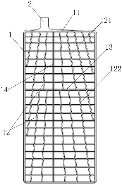
[0017] A battery grid such as figure 1 As shown, it includes a frame body 1 composed of frame bars 11, on which there are tabs 2, and inside the frame body 1 are a plurality of oblique ribs 12 distributed radially and a plurality of transverse ribs 13 connecting the oblique ribs 12.

[0018] The oblique ribs 12 are divided into the first type of oblique ribs 121 and the second type of oblique ribs 122; along the direction from the frame bar 11 where the tab 2 is located to the fr...


PUM


Abstract

The invention relates to a storage battery, in particular to a storage battery grid plate. The storage battery grid plate is realized through the following technical scheme that: the storage battery grid plate comprises a frame consisting of frame strips, wherein the frame is provided with a pole lug; radially-distributed oblique bars and transverse bars connected with the oblique bars are arranged in the frame; the oblique bars comprise the oblique bars of the first type and the oblique bars of the second type; along the direction from the frame strip on which the pole lug is to the frame strip opposite to the pole lug, the oblique bars of the first type start from the frame strip on which the pole lug is and end at one transverse bar, and the oblique bars of the second type start from the transverse bar and end at the frame strip opposite to the pole lug or end at the other transverse bar; the oblique bars of the first type and the oblique bars of the second type are distributed in a staggered mode; and at least one transverse bar is connected with terminal ends of a plurality of the oblique bars of the first type and is connected with starting ends of a plurality of the oblique bars of the second type. The storage battery grid plate is manly applied to storage batteries.

Description

technical field [0001] The invention relates to a storage battery, in particular to a storage battery grid. Background technique [0002] Existing battery grids, such as the "high-strength lead-acid battery grid" disclosed in the invention patent of Chinese Patent No. 90215614.4, are distributed with grid bars that make the grid a grid-like grid. , so that the grid nodes, that is, the intersections of the grid ribs, contain nodes in the shape of a "meter" or "X". Although the grid with this structure can effectively improve the transmission performance of the grid, it is due to multiple The oblique ribs are all intersected at one point of the transverse rib, so that this point of the transverse rib bears a greater force, especially the transverse rib in the middle of the grid plate bears the greatest force and is easy to break. Contents of the invention [0003] The object of the present invention is to provide a storage battery grid that effectively reduces the stress on...

Claims


Application Information

Patent Timeline
Patent Type & Authority Applications(China)
IPC IPC(8): H01M4/72
CPCY02E60/10
Inventor 郭伟杨新明庄建
Owner 长兴诺力电源有限公司
Why Eureka
Try Eureka