Device for reducing aerodynamic drag

A technology of aerodynamic resistance and engines, applied in the field of aerospace vehicles, can solve the problems of reducing payload, difficulty in using space shuttles, and designing bulky release devices, etc.

Inactive Publication Date: 2010-11-03
ASTRIUM GMBH
View PDF10 Cites 1 Cited by
  • Summary
  • Abstract
  • Description
  • Claims
  • Application Information

AI Technical Summary

Problems solved by technology

[0010] on the other hand, the back cover cannot be used during a space shuttle launch because it must be discarded before the rocket motors ignite, requiring a cumbersome release mechanism to ensure that no debris can damage the space shuttle or boosters
[0011] similarly, detachable movable units are difficult to use on the space shuttle because they are heavy and require mechanisms to operate them
[0012] In addition, the implementation of these systems is complicated, since they must be deployed when the rocket motor is ignited during atmospheric flight without itself creating additional drag
[0013] similarly, the use of active fluid injection devices would require fluid to be carried within the vehicle, which would reduce its payload

Method used


Image

  • Device for reducing aerodynamic drag
  • Device for reducing aerodynamic drag
  • Device for reducing aerodynamic drag

Examples


Embodiment Construction

[0021] The present invention proposes a device for reducing the aerodynamic drag of aircraft 1 (such as space shuttles and space launchers).

[0022] The principle of the invention is to adopt a passive device that can be eliminated by the rocket engine itself after the rocket engine is ignited. The non-powered device can also provide a very light solution and achieve reliability through its design.

[0023] The device of the present invention is designed to allow the rocket engine to properly ignite and completely clear the device after ignition, thereby avoiding the risk of debris falling to the ground.

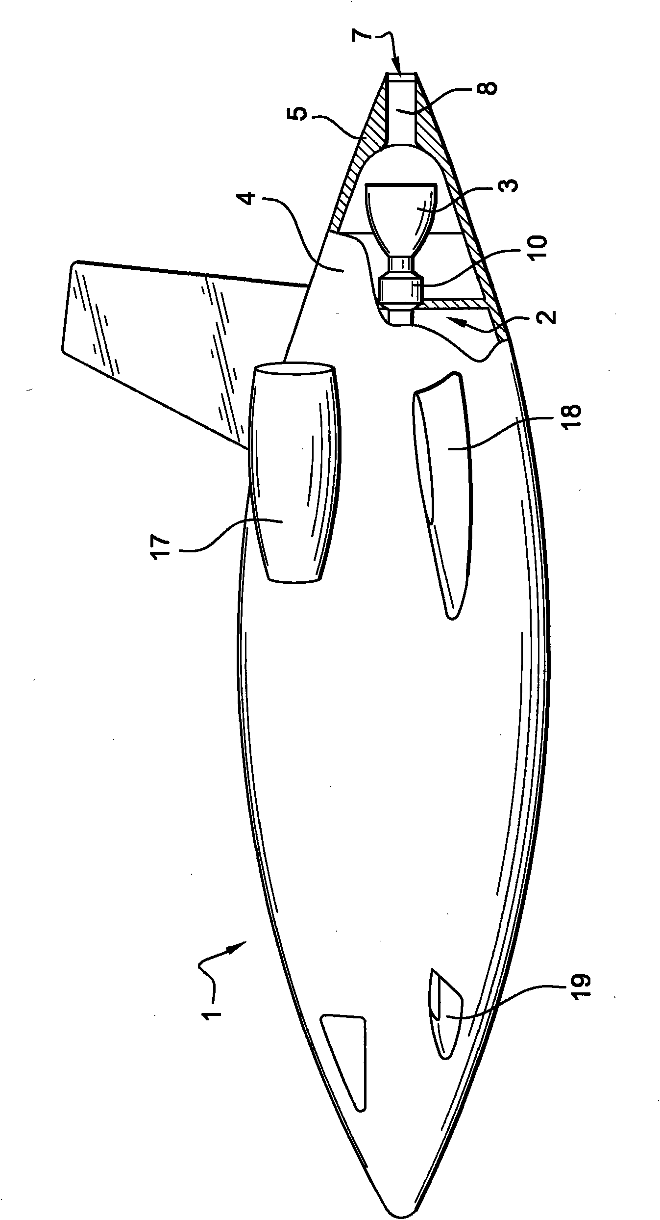
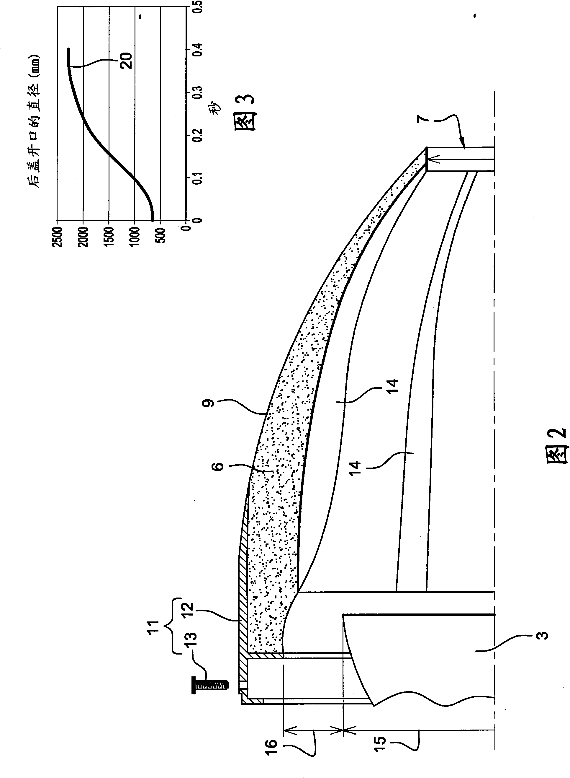
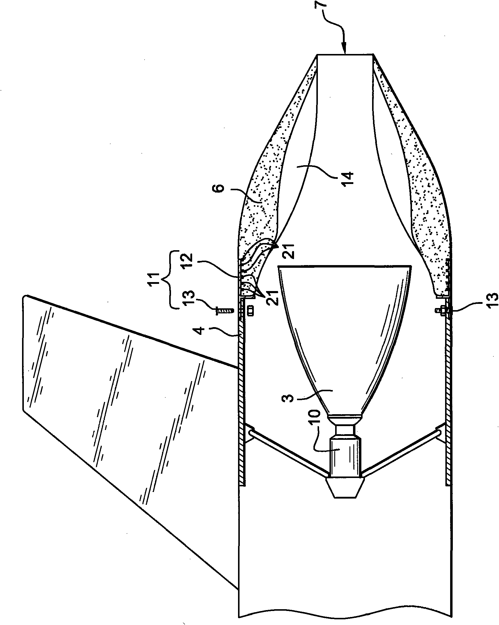
[0024] figure 1 The example shown is a space shuttle equipped with at least one engine 2 equipped with jet tube propulsion nozzles 3 projecting over the rear of the space shuttle fuselage 4.

[0025] As is conventionally known, the propulsion nozzle of the jet tube of the engine becomes wider as it leaves the rear of the aircraft fuselage.

[0026] The shielding device includes at l...


PUM


Abstract

The invention relates to a device for reducing the aerodynamic drag of a vehicle (1) provided with at least one engine (2) including a gas ejection nozzle (3) protruding from the rear of the vehicle fuselage (4) and flaring away from the rear of the vehicle fuselage, characterised in that it comprises at least one member (5) for masking at least a portion of the nozzle, made of a resorptive material (6) that can be eliminated in the nozzle flow once the engine is operating. The invention also relates to a spacecraft including the same.

Description

Technical field [0001] The present invention relates to a method for reducing the aerodynamic drag caused by the rocket engines of spacecraft such as space shuttles in the flight phases when these engines are not used, while allowing these engines to be in the atmospheric / non-atmospheric transition flight phase and the subsequent non-atmospheric flight phase Working device. [0002] Specifically, it is applied to aerospace vehicles including traditional aero engines for atmospheric flight and rocket propellers for extra-atmospheric flight. Background technique [0003] The resistance to the movement of the aircraft caused by the rear of the aircraft is called the base resistance. [0004] The fluid flow that is difficult to follow the rear contour of the moving aircraft becomes the turbulence behind the aircraft, which reduces the pressure at the rear of the aircraft and generates a strong resistance to the forward movement of the aircraft. [0005] There are passive solutions to red...

Claims


Application Information

Patent Timeline
Patent Type & Authority Applications(China)
IPC IPC(8): B64G1/00B64G1/14
CPCB64D27/023F42B10/40B64G1/002B64D29/04F42B15/00B64G1/14Y02T50/40
Inventor 格拉尔德·雷蒙德菲利普·布尔迪厄
Owner ASTRIUM GMBH
Why Eureka
Try Eureka