
Synchronous grouting simulation test platform of shield tunneling machine

A simulation test and synchronous grouting technology, which is applied in the direction of shaft lining, tunnel lining, underground chamber, etc., can solve the problem that the grouting simulation device cannot perform the simultaneous grouting simulation test of the shield tunneling machine

Inactive Publication Date: 2012-05-23
上海盾构设计试验研究中心有限公司 +1
View PDF1 Cites 2 Cited by
  • Summary
  • Abstract
  • Description
  • Claims
  • Application Information

AI Technical Summary

Problems solved by technology

[0008] The technical problem to be solved by the present invention is to overcome the defect that the existing grouting simulation device cannot perform the synchronous grouting simulation test of the shield tunneling machine, and provide a shield tunneling machine synchronous grouting simulation test platform, which can simulate the shield tunneling machine During the propulsion process, the process of synchronous grouting at the tail of the shield can be simulated at the same time with different technological conditions such as propulsion speed, grouting flow rate, and grouting pressure, so as to study the relationship between various process parameters and their influence on the grouting effect

Method used


Image

  • Synchronous grouting simulation test platform of shield tunneling machine
  • Synchronous grouting simulation test platform of shield tunneling machine
  • Synchronous grouting simulation test platform of shield tunneling machine

Examples


Embodiment Construction

[0020] The present invention will be described in further detail below in conjunction with specific embodiments and accompanying drawings.

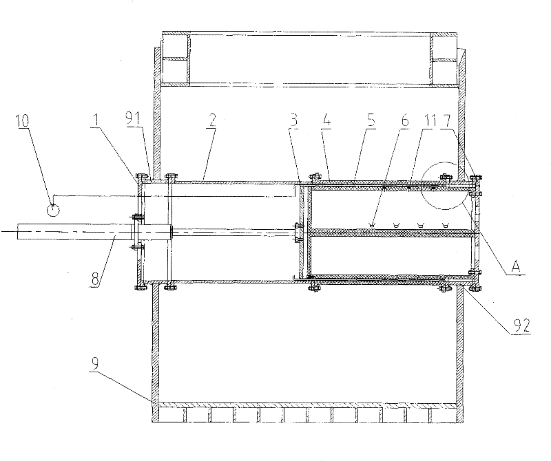
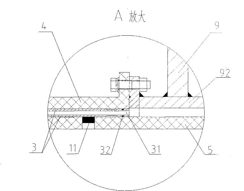
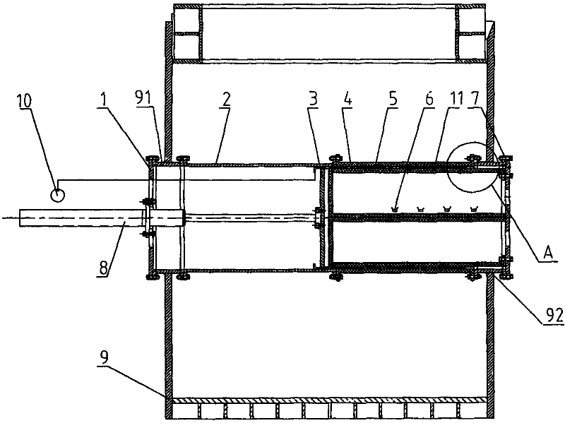
[0021] see figure 1 Schematic diagram of the structure of the present invention, the shield tunneling machine synchronous grouting simulation test platform includes soil box 9, left connecting pipe 91, right connecting pipe 92, left end cover 1, right end cover 7, simulated segment 5, simulated shield tail 3 , Propel hydraulic cylinder 8, guide barrel 2, transparent outer barrel 4, earth pressure sensor 11, camera 6 and grouting pump 10.

[0022] The soil box 9 is a square box structure made of steel, which is placed above the ground. The size of the soil box 9 is 2.5m in length, 2.5m in width, and 3m in depth, and can be filled with test soil inside. The left connecting pipe 91 and the right connecting pipe 92 are short tubular members made of steel, and the left connecting pipe 91 and the right connecting pipe 92 are coaxially welded a...


PUM


Abstract

The invention relates to a synchronous grouting simulation test platform of a shield tunneling machine, comprising a soil tank, a simulation tube piece, a simulation shield tail, a propelling hydraulic cylinder, a guiding barrel, a transparent outer barrel, a soil pressure sensor, a camera and a grouting pump, wherein the axis of the guiding barrel is horizontally and fixedly connected to the left side wall of the soil tank, one end of the transparent outer barrel is coaxially and fixedly connected with the guiding barrel, the other end is fixedly connected with the right side wall of the soil tank, the transparent simulation tube piece is coaxially sleeved in the transparent outer barrel and is fixedly connected with the right side wall of the soil tank, the camera is arranged in an inner cavity of the simulation tube piece, the soil pressure sensor is arranged on the barrel wall of the simulation tube piece, the simulation shield tail is coaxially sleeved in the periphery of the simulation tube piece and can axially slide along the inner barrel wall of the guiding barrel and the outer barrel wall of the simulation tube piece, a grouting hole is arranged in the barrel wall of thesimulation shield tail and is communicated with the grouting pump, and the propelling hydraulic cylinder can drive the simulation shield tail to do reciprocating motion. The invention can dynamicallysimulate and directly observe the whole process of synchronous grouting of the shield tunneling machine under different working conditions, thereby providing conditions for the test and the theoretical study of a synchronous grouting technique of the tunneling machine.

Description

Technical field: [0001] The invention relates to a simulation test device for tunnel shield boring machine construction, in particular to a shield tunneling machine synchronous grouting simulation test platform, which belongs to the technical field of tunnel construction engineering. Background technique: [0002] There are many ways to study the construction technology of underground tunnels, such as theoretical analysis, etc., and the test method is also a very important scientific method. The characteristics of the body and the interaction relationship between the soil and the machine. At present, some enterprises, scientific research institutions and universities at home and abroad have established relevant laboratories to design and build corresponding simulation test benches to carry out this specific engineering simulation test. For example, Shanghai Tunnel Engineering Co., Ltd. has developed a large-scale shield tunneling simulation test platform. To carry out the c...

Claims


Application Information

Patent Timeline
Patent Type & Authority Patents(China)
IPC IPC(8): E21D11/10
Inventor 庄欠伟戴志仁吕建中吴兆宇滕丽李毕华严晓华朱敏明陆晓华
Owner 上海盾构设计试验研究中心有限公司
Learn More