Pneumatic actuator

A technology of pneumatic actuators and cylinder blocks, which is applied in the direction of engine components, valve details, valve operation/release devices, etc., can solve the problems of piston rods, piston deformation, cylinder air leakage, etc., and achieve high reliability and long service life , the effect of compact structure

Inactive Publication Date: 2010-11-10
季忠庸
View PDF5 Cites 13 Cited by
  • Summary
  • Abstract
  • Description
  • Claims
  • Application Information

AI Technical Summary

Problems solved by technology

[0003] In order to overcome the problems of common pneumatic actuators in the prior art that easily cause deformation of the piston rod and piston and air leakage of the cylinde

Method used


Image

  • Pneumatic actuator
  • Pneumatic actuator
  • Pneumatic actuator

Examples


Embodiment Construction

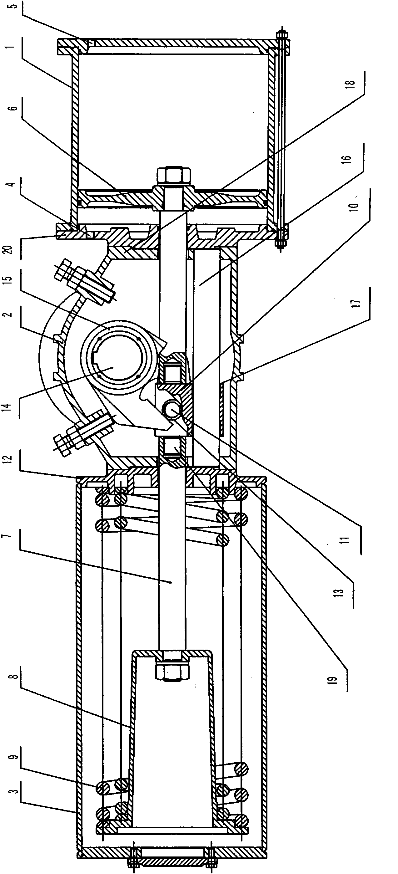
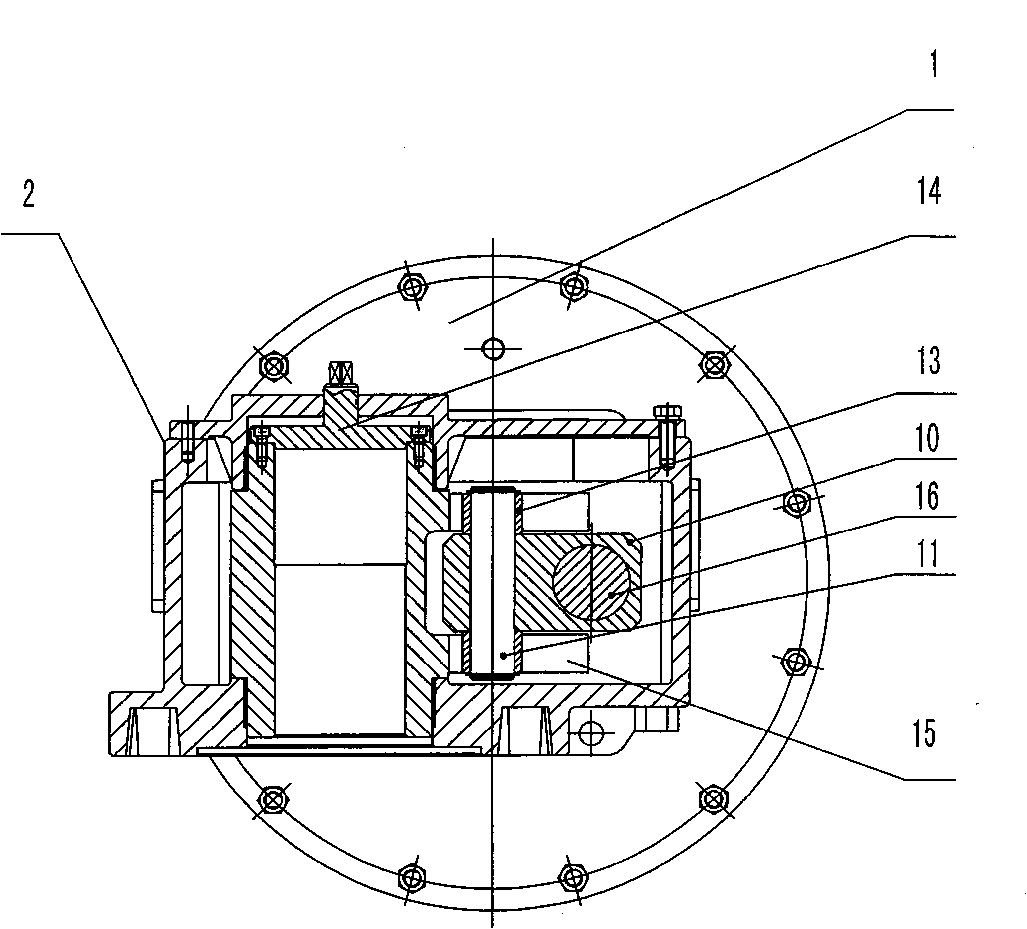
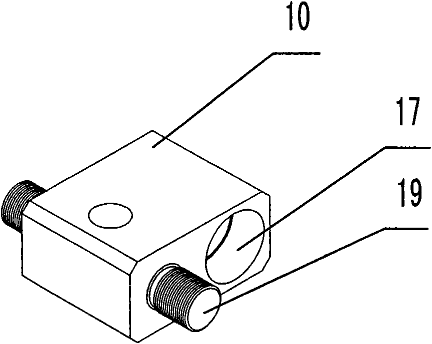
[0012] As shown in the figure, the present invention includes a connected cylinder block 1, an executive box body 2 and a spring cylinder body 3, wherein the end cover 12 on one side of the spring cylinder body 3 is connected with the executive box body 2 by screws, and the cylinder body 1 side is The end cover 20 is connected with the executive box 2 by screws. Air inlet 4 and exhaust port 5 are arranged on the cylinder body 1, the piston 6 in the cylinder body 1 is connected with the spring seat 8 in the spring cylinder body 3 through the piston rod 7 passing through the execution box body 2, and the outside of the spring seat 8 A return spring 9 is set, and the piston rod 7 is formed by docking the actuator block 10 in the middle. The roller shaft 11 is inserted on the actuator block 10, and the end of the roller shaft 11 is covered with a roller 13, and the roller 13 is connected to the output shaft in the actuator box 2. The shift fork 15 fixed on 14 matches, and the guid...


PUM


Abstract

The invention relates to a pneumatic actuator. The pneumatic actuator comprises a cylinder block, an actuating box body and a spring cylinder block which are connected with one another, wherein the cylinder block is provided with an air inlet and an air outlet; a piston in the cylinder block is connected with a spring seat in the spring cylinder block through a piston rod which passes through the actuating box body; a return spring is arranged outside the spring seat; the entire piston rod is formed in the middle through butt joint of an actuating block; a rolling shaft is inserted into the actuating block; a roller is sleeved outside the end part of the rolling shaft and matched with a fixed shift fork on an output shaft in the actuating box body; a guide rod which is parallel with the piston rod is arranged in the actuating box body; and the actuating block is provided with a guide hole and is in clearance fit with the guide rod through the guide hole. The defects of easy deformation of the piston rod and the piston and air leakage of the cylinder caused by an ordinary pneumatic actuator in a working process in the prior art are overcome. Due to specific design, the actuating block is matched with the guide rod through the guide hole and linear and stable running is kept. The pneumatic actuator has the advantages of compact structure, high reliability and long service life.

Description

technical field [0001] The invention relates to a pneumatic actuator. Background technique [0002] The pneumatic actuator is a control actuator for opening and closing the valve. Its structure generally includes a cylinder block, an execution box and a spring cylinder. The piston rod is connected with the inner chamber of the spring cylinder. When the piston and the actuator in the piston rod slide to make the shift fork and the output shaft in the actuator box rotate positively and negatively, the valve will open or close accordingly. In traditional pneumatic actuators, when the pressure of the air source pushes the piston, and the piston rod transmits the torque to the fork to rotate, the resistance generated by the rotation of the fork will force the actuator block to slide to the outside to generate force deformation, which will inevitably affect the piston rod. and other moving parts cause fatal damage, resulting in deformation of the piston rod and piston, and air le...

Claims


Application Information

Patent Timeline
IPC IPC(8): F16K31/122
Inventor 季忠庸
Owner 季忠庸
Why Eureka
Try Eureka