Real-time closed-loop measuring and tracking method of half-wave voltage of integrated electro-optical phase modulator

A phase modulator and integrated electro-optical technology, which is applied in the directions of optical radiation measurement, current/voltage measurement, measurement device, etc., can solve the problems of inability to meet high-precision sensor measurement, poor accuracy, etc.

Inactive Publication Date: 2010-11-10
ZHEJIANG UNIV
View PDF1 Cites 17 Cited by
  • Summary
  • Abstract
  • Description
  • Claims
  • Application Information

AI Technical Summary

Problems solved by technology

[0010] In the current research on optical fiber sensing technology, the accuracy of the original integrated electro-optic modulator phase modulator electro-optic phase half-wave voltage test method is poor, or it belongs to the open-loop test method, and the test accuracy is affected by the drift of the sampling circuit, so it cannot meet the requirements The application in high-precision sensing measurement requires a new measurement method that can measure half-wave voltage more accurately to meet the current situation of application in high-precision sensing measurement. The purpose of the present invention is to provide an integrated electro-optic phase modulator half-wave Real-time closed-loop measurement and tracking method of wave voltage to achieve precise and fast closed-loop measurement and real-time tracking of half-wave voltage, and this test method has nothing to do with the drift of the test circuit

Method used


Image

  • Real-time closed-loop measuring and tracking method of half-wave voltage of integrated electro-optical phase modulator
  • Real-time closed-loop measuring and tracking method of half-wave voltage of integrated electro-optical phase modulator
  • Real-time closed-loop measuring and tracking method of half-wave voltage of integrated electro-optical phase modulator

Examples


Embodiment Construction

[0047] The present invention will be further described below in conjunction with drawings and embodiments.

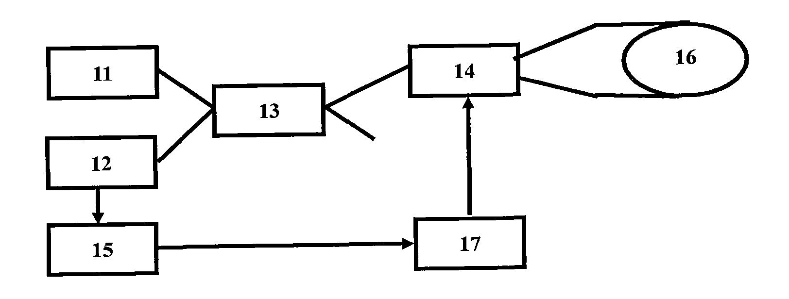
[0048] like figure 1 Shown is a schematic block diagram of a typical test system, in which the tested integrated electro-optic phase modulator 14, light source 11, photodetector 12, beam splitter 13 and fiber ring 16 constitute an optical Segneck fiber interferometer; the light source The light emitted by 11 is divided into two beams by the beam splitter 13, one of which is input to the electro-optical phase modulator under test, and then divided into two beams, and injected into the two ends of the fiber ring 16, respectively along the optical fiber The clockwise and counterclockwise directions of the ring 16 propagate, and the two beams of light are modulated by the time-delay difference of the integrated electro-optical phase modulator 14 , and the modulated waveform is generated by the modulation signal generator 17 . The light modulated by time delay difference re...


PUM


Abstract

The invention discloses a real-time closed-loop measuring and tracking method of the half-wave voltage of an integrated electro-optical phase modulator. One Sagnac fiber optic interferometer is used as a measuring device, and the phase of the fiber optic interferometer is modulated by the measured integrated electro-optical phase modulator. An adopted phase modulating signal comprises four modulation steps A, B, C and D, the duration time of each modulation step equals to the transition time of the Sagnac fiber optic interferometer, the modulation voltage signals of the four modulation steps are respectively 0, V, 4V and V, and the magnitude of V is adjustable. The interferometer output signals corresponding to the phases B and C are measured by using a sampling circuit, the magnitude of V is adjusted according to an established policy until the measurement precision is met, and thus, the real-time closed-loop measurement and tracking to the half-wave voltage can be realized. The method has the characteristic of real-time measurement due to the adoption of closed-loop measurement, the method can be used for tracking the half-wave voltage, and the precision and the reliability of measurement are high and can not be influenced by the drift of the sampling circuit.

Description

technical field [0001] The invention relates to a signal processing method in an optical fiber gyroscope sensor, in particular to a real-time closed-loop measurement and tracking method for half-wave voltage of an integrated electro-optic phase modulator. Background technique [0002] Half-wave voltage is a parameter used to measure the modulation performance of integrated electro-optical phase modulators (often referred to as phase modulators, modulators, etc.), which is defined as the voltage that needs to be loaded on the modulation electrode to make the integrated electro-optical phase modulator generate π phase Voltage, half-wave voltage and electro-optic phase modulation coefficient are an equivalent parameter. Both are parameters used to describe the phase modulation efficiency of the phase modulator. The electro-optic phase modulation coefficient is defined as the ratio of the optical phase modulation generated by the phase modulator to the voltage applied to its ele...

Claims


Application Information

Patent Timeline
Patent Type & Authority Applications(China)
IPC IPC(8): G01J9/02G01R19/00
Inventor 陈杏藩周虎刘承舒晓武
Owner ZHEJIANG UNIV
Why Eureka
Try Eureka