Shoe-drying machine

The technology of a shoe drying machine and main body is applied in the direction of cleaning boots and shoes, cleaning equipment, household appliances, etc., which can solve the problems of collecting devices without dripping water, damp shoes, waste of electric energy, etc., achieving a simple and fast control method, and preventing pollution. , the effect of reducing energy waste

Inactive Publication Date: 2010-11-17
NINGBO HONGTONG ELECTROMECHANICAL +1
View PDF5 Cites 6 Cited by
  • Summary
  • Abstract
  • Description
  • Claims
  • Application Information

AI Technical Summary

Problems solved by technology

[0002] In order to solve the problem of many people wearing shoes, the inside of the shoes is wet and cannot be dried in time, people have designed a shoe drying machine. At present, with the continuous development of technology, the structure design of the shoe drying machine is more reasonable, and the function is getting better and better. many
[0003] Existing shoe dryers are only equipped with a pair of air outlet pipes, that is, the existing shoe dryers can only dry a pair of wet shoes at the same time, so the efficiency of the drying device is low and cannot meet the needs of existing families. Use requirements, and wet shoes may drip water, and the existing shoe drying machines do not have a drip collection device, and at the same time the length of the support tubes of the shoe hanging shoes of the existing shoe drying machines are all fixed lengths, which cannot Adapt to the practical requirements of different shoe types, and the existing shoe drying machine uses a switch to control the work of all devices, which may cause some devices to work even when they do not need to work, which causes a waste of electric energy

Method used


Image

  • Shoe-drying machine
  • Shoe-drying machine
  • Shoe-drying machine

Examples


Embodiment Construction

[0025] The present invention will be further described below in conjunction with accompanying drawing,

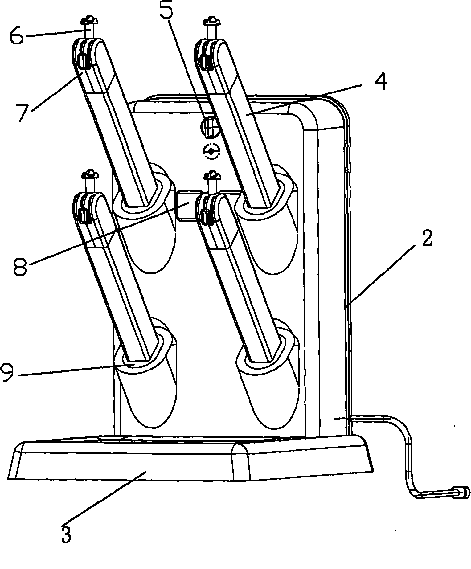
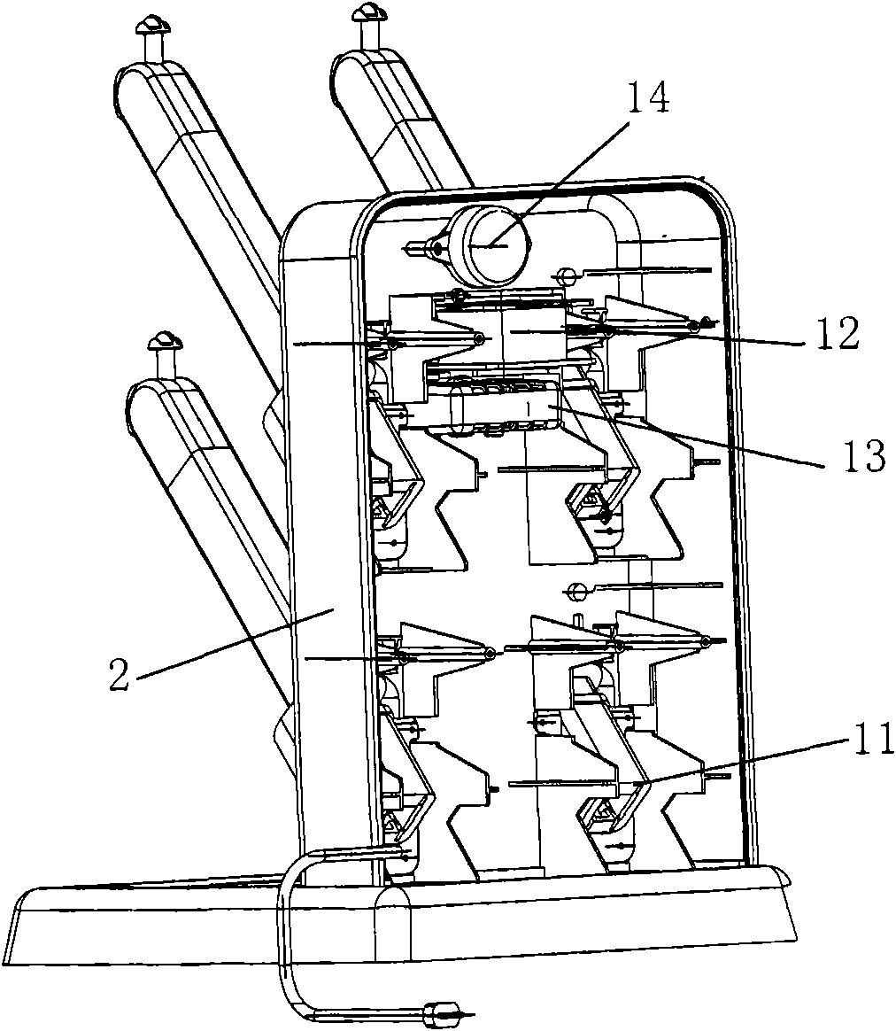
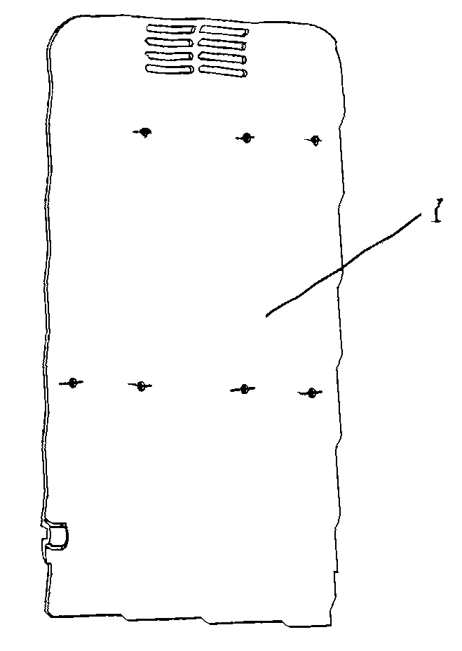
[0026] like Figure 1 to Figure 6 The shoe drying machine shown includes a base 3, a main body 2, a rear cover 1, a blower device 12, and an air outlet device 4 with a heating device. The main body 2 is a hollow cavity, and the rear cover 1 is connected to the main body. , the main body 1 is closed into a shell, and a timing device 14 is arranged on the upper part of the cavity of the main body 2. The timing device 14 is connected with a timing knob 5, which is convenient for the user to adjust the drying time. The main body 2 below the timing device 14 Air blowing device 12 is arranged on the top, and the main body 2 below the blowing device 12 is provided with a pallet 13. We put a perfume device on the pallet 13, and the perfume device is constantly volatilized, and the blast device 12 agitates the The air flows to make the air in the main body 2 mix with the fragrance,...


PUM


Abstract

The invention relates to the field of a drying device, in particular to a shoe-drying machine which can simultaneously dry and deodorize a plurality of shoes. The shoe-drying machine comprises a base, a main body, a rear cover plate, a blower device and an air outlet device with a heating device, wherein the heating device is arranged in the air outlet device, the main body is an open cavity, the rear cover plate is connected to the main body to form a closed cavity, the main body is connected to the base, the blower device is arranged in the main body, and the air outlet device is connected with the front end surface of the main body. The shoe-drying machine also comprises a control device, the end part of the air outlet device is provided with a vertical switch device supported by an elastic device. The invention can singly control the heating device to avoid unnecessary energy waste and has the deodorization function.

Description

technical field [0001] The invention relates to the field of drying devices, in particular to a shoe drying machine capable of simultaneously drying a plurality of shoes and deodorizing and enhancing the fragrance of the shoes. Background technique [0002] In order to solve the problem of many people wearing shoes, the inside of the shoes is wet and cannot be dried in time, people have designed a shoe drying machine. At present, with the continuous development of technology, the structure design of the shoe drying machine is more reasonable, and the function is getting better and better. many. [0003] Existing shoe dryers are only equipped with a pair of air outlet pipes, that is, the existing shoe dryers can only dry a pair of wet shoes at the same time, so the efficiency of the drying device is low and cannot meet the needs of existing families. Use requirements, and wet shoes may drip water, and the existing shoe drying machines do not have a drip collection device, an...

Claims


Application Information

Patent Timeline
Patent Type & Authority Applications(China)
IPC IPC(8): A47L23/20
Inventor 袁罗强潘宏毅宁程磊
Owner NINGBO HONGTONG ELECTROMECHANICAL
Why Eureka
Try Eureka